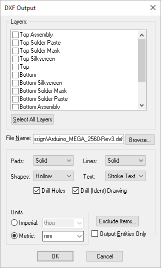
Use this dialog to export Pulsonix design data in DXF format. DXF (Data Exchange Format), is a two-dimensional file format recognised by most desktop based mechanical drawing (MCAD) packages.
Shortcuts
Default Keys: None
Default Menu: Output
Command: Output DXF
Locating this option
Available from: Output menu > DXF > option
How To Use The DXF Export

Layers
Select the Layer or Layers required for output. These are selected when the check box is ‘ticked’. Then select the output options required.
If you select a layer span (such as
File Name
Type the file name required. By default, the option will use the design name and the file extension .dxf. Use the Browse button to define the folder required for the output.
DXF Objects
The PCB DXF output defines objects within the layout at one of four categories, Lines, Pads, Shapes and Text. Each of these categories can be output using a different style. These are, for Lines:
Solid - a solid filled line as true thickness of the shape it represents
Altsld - as Solid but uses an alternative style for the shape
Altsld2 - as Solid but uses an alternative method for defining the line width
Altsld3 - as Altsld2 but with rounded corners
Segsld - outputs each segment of the shape and fills the segment
Seghol - outputs each segment of the shape but uses an unfilled shape to represent each segment
Centreline - a single centre line of the line it represents
For Pads and Shapes, these are Solid (as defined above) and:
Hollow - similar to centre line except the outside edge of the circle is represented by an outline.
For Text, these are:
DXF Font - normal text output but uses the font defined by the recipient system
Stroke Text - text broken down into individual entities and represented as strokes or lines.
For a PCB or Panel Design extra options are:
Drill Holes - include drill holes for layer spans selected in the layers listbox.
Drill (Ident) Drawing - include drill drawing letters or symbols as would normally be shown on a drill drawing plot.
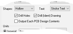
For a Panel Design there is another option: Output Each PCB Design Contents see below under Panel Editor.
Units
You can change the Units that you want your DXF sizes and coordinates to be output in, by selecting Imperial or Metric and by selecting the unit name from the appropriate dropdown box. By default the units used are your design units.
Exclude
To Exclude individual design items from the output file. You should click the Exclude Items button to enter the Exclude Items dialog to specify what you want excluded.
Output Entities Only
The Output Entities Only check box does not output a layer table at the start of the file. Use this if combining plots, i.e. the first plot has this option unchecked and other plots have it checked, or if adding a plot from the PCB to an existing mechanical drawing.
Panel Editor
For a Panel Design there is an additional option:
Output Each PCB Design Contents
Check this to specify that each PCB item in the panel will be replaced by the full contents of its PCB design file. Leave it unchecked if you are just producing a quick check panel output and only want to output the items you see in the PCB instances in the panel design.

If you are producing DXF output for a Panel design, three extra layers will be created in the output file containing the three types of panel shapes. Each layer will only be created if the design contains the appropriate type of panel shape.
Panel Outlines will be created on a “_PANEL_OUTLINE ” layer
Panel Tab-Routs are created on a “_PANEL_TAB_ROUTE” layer
Panel V-Score lines are created on a “_PANEL_V_SCORE” layer.
MCAD Systems
Mechanical CAD (Computer Aided Design) systems are used to create the mechanical aspects of the design process. Aspects which the PCB or Schematics design editor programs are not well suited.
These programs can exchange files through an intermediate format, most commonly, DXF for desktop based systems such as AutoCAD.
Saving DXF Dialog Settings
DXF Output saves all of the selected settings and layers to the registry for Schematics and PCBs. This means that in addition to saving the settings to the registry when outputting a DXF file via the Output menu, the settings can also be saved to the design through the CAM/Plot mechanism where the plot will keep track of the output settings.