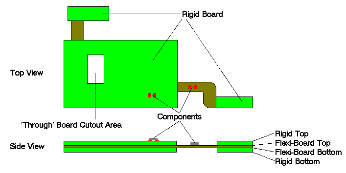
A flexi-rigid board is a composite of a flexi-board, with rigid board areas applied to the surface. Components can be placed on the outer surface of the rigid areas and optionally to the exposed flexi-board surface as well. This effectively means that the board outline is different on some layers.
This can be achieved by defining a Flexi-Board layer span for the flexi-board ‘inner’ layers (Flexi-Board Top to Flexi-Board Bottom), with the Rigid Top and Bottom layers being the normal Top and Bottom electrical layers (other layers can be defined as required). You can then create a board outline to define the shape of the flexi-board and change the layer of this board to the Flexi-Board span. Create multiple board outline shapes to define the Rigid Board parts (these will usually be a subset (or near subset) of the flexi-board shape). The Flexi-Board shape will override the Rigid Board shapes within its span, so tracks can be drawn right across from the Rigid section to the exposed Flexi-Board section on these layers.
Components can be legally placed on the outer layers within the Rigid Board outlines. You can also define the Flexi-Board Top and Bottom layers as Allowing Normal Components, you can then use Change Layer on components to place them on these layers, and they can then be legally placed in the exposed areas. Surface mounted components should have their layer changed to either of the layers defining the exposed surface of the Flexi-Board span. Through-hole components should have their layer changed to the actual Flexi-Board span. Each of the through-hole pads will be automatically changed to be on the Flexi-Board span.
Any components on the Top or Bottom side of the board, but outside of the Rigid board areas will be marked in error by the Component Spacing Design Rule Check. Similarly, components that have been changed to the Flexi-Board layer, but have not been moved from a Rigid section to an exposed Flexi-Board section will also be checked.

Alternative Method of producing Flexi-rigid boards using cutouts
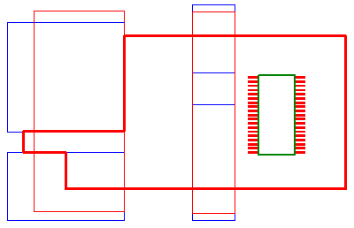
The method of applying cutouts to spans also supports another methodology of producing flexi-rigid boards. This is where Board Area Cutouts are used on the flexible layers so that when the main board outline is milled or routed, it produces a flexi-rigid solution.
The picture below shows a PCB design in Pulsonix. Each of the two red board cutout areas shown is actually two areas, one on a span from the top of the board to its opposite face above the top flexible layer, and the other from the bottom of the board to its opposite face just below the bottom flexible layer. The other four blue board cutout areas are on a span from the top flexible layer to the bottom flexible layer. The thick Board Outline is then used to create the overall design shape on each of the three layer spans.

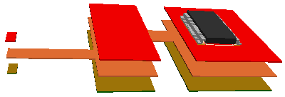
When viewed in the 3D Viewer, the three separate sections of the board can be seen as follows:

Related Topics
Board Cavities | Board Bending | Change Layer | Insert Area | Insert Board | Technology - Layers | Technology - Layer Spans