Insert Free Pad is used to insert a floating (non-component) pad into a PCB design. Use them for any special situation where Component Pads, Vias or Mounting Holes are not appropriate.
For example, use a free pad as a test land. These can be added directly using Insert Testpoint.
Another example is you may require a row of additional pads for which to solder wire connections to during prototyping.
Free pads can be added to the design without requiring a component, and without the need to name them, and thus do not show up as part of the netlist.
Shortcuts
Default Keys: None
Default Menu: Insert
Command: Insert Pad or Insert Pin
Locating this option
Available from: Insert menu > Pin option
Available from: Insert menu > Pad option
How To Insert A Free Pad
- Select the Insert Pad icon from the PCB Toolbar. Or:
- From the Insert menu, select Insert Pad
The default Pad as defined in Options, Defaults will then be visible at the end of your cursor. You may place the Pad at the required position in the design. Click the mouse to release the Pad positioning operation.
How To Change The Pad Shape and Layer
You may change the Pad shape and carry out other operations associated with the Pad before or after final positioning.
Before final positioning:
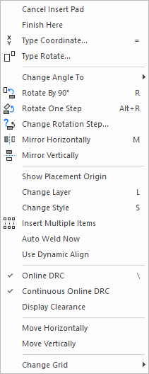
With the Pad visibly positioned at the end the cursor right click the shortcut menu opens :

You may then:
Rotate the pad
Mirror the pad (if surface mounted)
Change the Layer for the pad
Change the style of the pad
Also under this menu you may select Obey Design Rules which will restrict positioning of the Pad to conform with the design rules settings within the Technology File
You may select Display Clearances, which presents a visible warning if you are positioning a Pad too close to another item within the design
You may change the grid settings or work with no grid under Change Grid