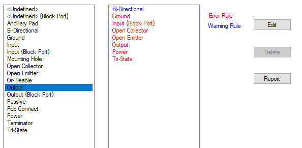
Electrical Rules Checking will check the connectivity of each net. The rules defined here specify which types of pins are allowed to be connected. You can use this to check that, for example, two outputs are not connected together, or that a power pin is not connected to ground.
Shortcuts
Menu: Setup
Default Keys: T
Command: Technology
Locating this option
Available from: Setup menu > Technology option > Pin Type Pair Rules tab
How to use Pin Type Pair Rules

Navigation
Press the Edit button to add a rule to the list,. To edit an existing entry, select it and press the Edit button. If the right hand pane is empty for a selected Pin Type, this means that no rule is defined for it.
Remove rules from the right hand pane by selecting it and pressing the Delete button.
For a full list of all the ERC rules defined for your design, press the Report button.
The List of Pin Types
The left hand column lists the known Pin Types. Pin Types are user defined, with Pulsonix supplying a default set of rules for you to use. You can also edit your own Pin Types and rules. Rules are edited in this dialog, Pin Types are edited using the Pin Types tab in your design Technology. Only Pin Types defined in Pin Type Names page can be used.
No Connect types are not listed because they have a fixed rule that nothing can connect to them.
An additional
Pin types which are checked as Allow on Block Ports have an additional {Block Port} entry. This is because Block Ports have different rules applied to them. The corresponding Block Instance Pin uses the normal rules. (That is to say, the connectivity allowed to the inside of a block port is different to that allowed to the outside).
For example, consider an Output pin on a block. Inside the block, a component Output pin can be connected to the Output block port. Outside the block, the block instance pin should not be connected to another Output pin. So there would be a rule to prevent an Output pin being connected to another Output pin, but no rule to prevent an output pin being connected to an Output {Block Port} pin.
Viewing Rules for a particular Pin Type
Select a Pin Type from the left hand column, all the rules defined for that pin type are shown in the right hand column.
Rules that result in an electrical rules error, are shown in the Error colour. Similarly rules that will only result in a warning, are shown in the Warning colour. Note: These colours are fixed and cannot be changed.
If the combination of pin types are ignored by the electrical rules checking, then they do not appear in the right hand column.
Adding Rules for a particular Pin Type
- Select a Pin Type from the left hand column.
- Click the Edit button or double click on the Pin Type.
- This opens the Edit Pin Pair Rule dialog from where you can define how the rules interact with each other.
Removing Rules for a particular Pin Type
- Select a Pin Type from the left hand column.
- Select the other Pin Type from the right hand column.
- Click the Delete button.
- Select the Apply button on the dialog to apply the changes to the design. These rules will now be used when the online ERC option is used and when the Electrical Rules Checking (ERC) is performed.
Related Topics
Pin Type Names | Edit Pin Type Pair Rule | Electrical Rules Check | Insert - Block Port | Properties - Block Ports