Insert Dimension is used to dimension items within the design, or gaps between items within the design. It is used to display (in the form of a dimension) lengths of items, radius of arcs and angles between lines.
Dimensions can be snapped onto design items in order to start or end on exact positions, and can be attached to those design items. This means if the design item is moved, the dimension is automatically stretched and its measurement updated. Drag the dimension end off the item to unattach it. You can also highlight the attached half of dimensions in a different colour if you want to see which dimensions are attached in the design.
Shortcuts
Default Menu: Insert
Default Keys: None
Default Menu: Insert
Command: Insert Horizontal Dimension
Default Keys: None
Default Menu: Insert
Command: Insert Vertical Dimension
Default Keys: None
Default Menu: Insert
Command: Insert Free Dimension
Default Keys: None
Default Menu: Insert
Command: Insert Radial Dimension
Default Keys: None
Default Menu: Insert
Command: Insert Angular Dimension
Locating this option
Available from: Insert menu > Dimension options
Available from: PCB Toolbar > Dimension icon
How To Insert A Dimension
First set up your required dimensions appearance and units type using the Dimension Defaults dialog. This will ensure that all dimensions added will have the same appearance, and their measurements will be displayed using the same units. These default settings can be setup in your Technology Files so that new designs will be ready to add dimensions in your preferred style.
Individual dimensions can have a different appearance applied after being added to the design by selecting them and using the Properties option.
Select Insert Dimension from the Insert menu, or use one of the shortcuts mentioned above.
You are now in one of the Insert Dimension modes, by clicking the right hand mouse button you will see the Insert Dimension shortcuts menu:
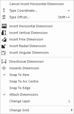
Select the type of dimension required.
Snap To Item
This option will cause the linear dimension start or end point to be at the closest edge of the item selected. If a pad is being dimensioned then the snap point will be at the pad’s centre.
Snap To Arc Centre
This is available when snapping to an item, will cause the dimension to snap to the centre of a selected arc, rather than the nearest point on it.
Snap To Edge
When snapping to an item, will cause the dimension to snap to an edge of a line or pad. The default is the near edge. This is available in linear and radial dimensions.
Attach Dimensions
This option is available if you are adding a linear dimension with Snap To Item on, or if you are adding a radial or angular dimension. If checked the dimension will be attached to the items that are picked for the start and end points. This means if the design item is moved, the dimension is automatically stretched and its measurement updated. If the item is deleted or moved to the bin the attached dimension will be left unattached.
Directional Dimension
This option is available when adding a horizontal or linear dimension only. It changes the dimension from being a simple two arrow length dimension, to being part of a series of single arrow dimensions measuring distances from a zero base line. The default measurement text on directional dimensions is placed in a position above the single end arrow.
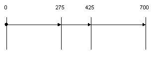
The procedure for adding directional dimensions is described in more detail below.
Inwards Dimension
This option will cause the arrows to be positioned outside the outer edges of the dimension, pointing inwards.

If Inwards Dimension is deselected then the arrows will be positioned within the dimension, pointing outwards. This is the normal mode of operation, but the arrows will flip the other way if the text does not also fit within the dimension.

The next steps depend on which type of dimension you are adding.
To Insert A Linear Dimension
Use these options to dimension lengths of items and gaps between items in the design.
-
Select Insert Horizontal Dimension from the above shortcut menu.

or
Select Insert Vertical Dimension from the above shortcut menu.

or
Select Insert Free Dimension from the above shortcut menu.
A free angle dimension can be used to dimension items or the spacings between items that do not lend themselves to standard orthogonal dimensioning.
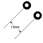
-
Make sure the option Directional Dimension is not set. The procedure to add directional dimensions follows next.
-
Select Snap to Item, Snap To Arc Centre and Inwards Dimension to your preference.
-
Single click to pick the position to start the dimension from, or (if using Snap To Item) pick the item you wish to snap the dimension on to. The dimension will now be drawn on the screen.
-
Move the mouse to position the end of the dimension. The dimension text will be automatically updated to show the measurement between the dimension start and end arrows.
If adding a horizontal or vertical dimension, a documentation line will be added from the moving start arrow head to the original start position.
If required, right click the mouse to use the shortcut menu to change the type of linear dimension you are adding, or to change the layer of the dimension, or to change the grid you are using.
-
Single click to pick the position to end on, or (if using Snap To Item) select the item you wish to snap the dimension on to.
-
Move the mouse to alter the offset of the linear dimension arrows from their original positions. Documentation lines will be drawn from the moving arrow heads to the original points of the dimension. Use the shortcut menu to change the grid that the dimension is moving on.
-
Single click to finish the dimension.
To Insert A Directional Dimension
Use this option to dimension multiple positions relative to a common base line.
-
Select Insert Horizontal Dimension from the above shortcut menu.
or
Select Insert Vertical Dimension from the above shortcut menu.
-
Select option Directional Dimension from the context menu.
-
Select any snap options to your preference.
-
Single click to pick the position to start the dimension from (point A in the diagram below), or if using Snap To Item pick the item you wish to snap the dimension on to. The dimension will now be drawn on the screen with a documentation line representing the zero base line.

-
At this point you can switch the dimension from horizontal to vertical if you are going the wrong direction.
-
Move the mouse to position the end of the dimension. The dimension text will be automatically updated to show the measurement between the base line and the dimension end arrow.
If required, right click the mouse to use the shortcut menu to change the layer of the dimension, or to change the grid you are using.
-
Single click to pick the position to end the first dimension on (point B in the diagram below), or if using Snap To Item pick the item you wish to snap the dimension on to. A documentation line will be drawn to show the end of the dimension.
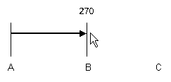
-
Move the mouse to alter the offset of the directional dimension arrows from their original positions. The documentation lines will be drawn from the moving arrow heads to the original points of the dimension.
-
Single click to finish the dimension at its required offset. The base line will change into a separate dimension with the value zero and a filled circle as its marker. The next directional dimension will now start from the base line ready for you to move it to the next point you want to measure to.
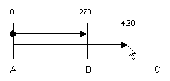
-
Single click to pick the position to end the next dimension on (point C in the diagram below), or if using Snap To Item pick the item you wish to snap the dimension on to. A documentation line will be drawn to show the end of the dimension.
Drag the dimension to its required offset. This would usually be placed directly over the previously added dimension to form a smooth line, but can be placed higher or lower if required. Use Cancel to finish the dimension when all measurements have been added, the current dynamic dimension will be discarded. The result for our example is three dimensions added to document positions B and C from point A.
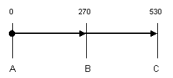
-
If you want to add another directional dimension to a series of dimensions already in the design, use Snap To Item and pick the bottom of the existing base line as the start point for the dimension. If the base line was attached to an item, your new dimension will also be attached to the same same item.
To Insert A Radial Dimension
Use this option to dimension the radius of an arc or circle within the design.

Before starting, make sure you have set up the Dimension Defaults required for your radial dimensions. Within the Dimension defaults there is a section specifically for the appearance of Radial Dimensions as follows:
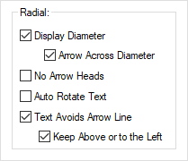
Display Diameter - Check this box if you want the dimension text to display the diameter of the circle or arc instead of the radius.
Arrow Across Diameter - If displaying diameter text, check this box if you want the arrow to cross the whole diameter of the circle or arc instead of just to the centre.
No Arrow Heads - Check this if you do not want arrow heads shown in your radial dimensions.
Auto Rotate Text - Check this if you want the dimension text to take the same angle as the dimension arrow.
Text Avoids Arrow Line - Use this to force the default position for the text to be moved a little so that the arrow tail lines are not broken.
Keep Above or to the Left - Use this to force the default position for the text to be always above or to the left of the arrow tail lines.
If all switches are checked the radial dimension will look like this:
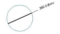
You are now ready to add the dimension as follows:
-
Select Insert Radial Dimension from the Insert Dimension shortcut menu.
-
Select Inwards Dimension to your preference. Snap to Item is not relevant as you must always pick an arc to snap to, but select Attach Dimensions if you want the dimension to be attached to the circle or arc.
-
Single click to pick the arc or circular item to dimension the radius of. The radial dimension will now be drawn on the screen. If displaying the radial diameter the arrow will be drawn completely across the circle, through the centre, and the diameter of the arc will be shown. Otherwise a line will be drawn from the arc’s centre to a point on it’s circumference and the dimension text will show the radius of the arc.
-
Move the mouse to change the angle of the dimension.
If the cursor is moved outside of the arc or circle, a documentation line will be added from a position on the arc to the cursor position and the text will be moved from inside the arrow, to the end of the documentation line.
If required, right click the mouse to use the shortcut menu to change the layer of the dimension, the Inwards Dimension preference, or to change the grid you are moving on.
-
Single click to finish the dimension.
To Insert An Angular Dimension
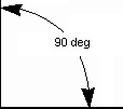
Use this option to dimension the angle between any two lines in the design.
-
Select Insert Angular Dimension from the Insert Dimension shortcut menu.
-
Select Inwards Dimension to your preference. Snap to Item is not relevant as you must always pick two lines, but select Attach Dimensions if you want the dimension to be attached to the lines in case they are moved in the design.
-
Single click on the first straight line, or on a corner between two straight lines. The picked line or lines are drawn selected. If a corner was picked, move to step 5.
-
Single click on a second straight line that is not the same angle as the first line. The picked line is drawn selected.
-
The angular dimension will now be drawn on the screen, between the two selected lines. The dimension text shows the angle between these lines.
Move the mouse to position the arrows of the dimension. As the cursor crosses one of the lines the dimension changes from an internal angle to an external angle and vice-versa. If the cursor moves past the end of one of the lines, a documentation line is drawn from the end of the line to the moving arrow head.
If required, right click the mouse to use the shortcut menu to change the layer of the dimension, the Inwards Dimension preference, or to change the grid you are moving on.
-
Single click to finish the dimension.
How To Change The Dimension Layer
- This can be done whilst adding the dimension, or after adding with the dimension selected. Right click the mouse to use the Change Layer option from the shortcuts menu.
- Use the Change Layer dialog to select a new layer for the dimension
How To Change The Dimension’s Line and Text Styles
- After adding the dimension, select the part of it you wish to change (arrow, documentation line or text). Right click the mouse to use the Change Style option from the shortcuts menu.
- Use the Change Style dialog to select a new style for the dimension part.
How To Move The Dimension Text
After adding the dimension the text will be in it’s default position. You may position the text anywhere by dragging it or using the Move option.
Note: If you want to put the dimension text back to it’s default position, select the text and right click the mouse to use Reset Text Position from the shortcut menu.
How To Alter The Dimension’s Appearance
First set up your required dimensions appearance and units type using the Dimension Defaults dialog and Dimension Units Defaults. This will ensure that all dimensions added will have the same appearance, and their measurements will be displayed using the same units. These default settings can be setup in your Technology Files so that new designs will be ready to add dimensions in your preferred style.
In the defaults dialog choose the required settings to best match your required drawing standards. Leaving the Text Avoids Arrow Line boxes unchecked will insert the text into the middle of the arrow lines which conforms to the ISO standard, whereas checking the Text Avoids Arrow Line and Keep Above or to the Left boxes will place the text above or to the left of the arrow lines and conforms more to the DIN standard.
Using the defaults dialog choose to add a standard Tolerance string to the end of the measurement text for each type of dimension. The tolerance text can be a different size to the measurement text and can be defined on two lines to easily represent a different plus and minus value.
Use Colours - Doc Shapes to change the colour of dimensions. You can also highlight the attached half of dimensions in a different colour if you want to see which dimensions are attached in the design.
Use Properties - Dimensions to alter the following properties:
- Dimension: Length Units or Angle Units, Decimal Point Character.
- Radial Dimension: Display Diameter, and draw the Arrow Across the Diameter.
- Arrow:Line style, Head Appearance and Size, Text Gap and Arrow Offset.
- Documentation Line: Line Style, Start Gap, Extended Length and Visibility.
- Documentation Text: Style, Alignment, Angle and Position. Avoid Arrow Line and Auto Rotate Text.
- Tolerance: Optionally include a tolerance value at the end of the dimension text, using its own text style.
Related Topics
Dimension Defaults | Dimension Units Defaults | Technology - Text | Move | Place Dimension | Stretch Dimension | Dimension Properties