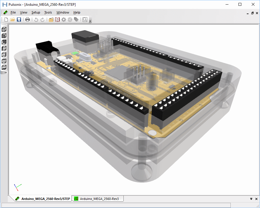
The 3D Viewer is an interactive environment where you can visualise your PCB in a realistic 3D form. You can also move components, add and move enclosures and detect/resolve any clashes.
Shortcuts
Default Keys: None
Default Menu: 3D Design
Command: 3D Viewer
Locating this option
Available from: 3D Design menu > 3D Viewer option
Using the 3D Viewer
On selection of 3D Viewer option, the 3D View containing referenced STEP models is generated and the 3D editor launched:

Preview Contents and Settings
Settings that will be used in both the STEP file output and within the 3D Preview window are controlled using the 3D Settings dialog.
Note: by selecting the Advanced Settings check box and any of the check boxes within it, you will increase the size of the STEP files and will also decrease the loading speed into the Preview window.
Model Priority in the Viewer
The viewer will prioritise models that it uses. If a STEP model is available it will always use that first, then it will look for a matching 3D Packages if the STEP model is not available. If neither of these are available, the viewer will then use the Component Height attribute if one is defined. Finally, it will use a built in height value of 2mm to provide a basic shape.
The 3D Toolbar
The 3D toolbar is automatically displayed (normally to the left hand side bar).

Looking from left to right, the toolbar icons are Axonometric, Front, Back, Left Side, Right Side. Top and Bottom, If you hover on the icon, the name of the view will be revealed.
Axonometric is the perspective view controlled from the 3D Settings View page.
Rotating the View
The initial view will be sized to give a reasonable picture based on the size of your board. This will be a perspective projection in a 3D view. If you wish to rotate the board in the window, press and hold the right hand mouse button and move the mouse. As you move the mouse, the view will spin. Moving it left and right will spin the board around the Y axis, moving it up and down will spin around the X axis. With practice you will find you can spin the board to the desired angle very easily.
Zooming In and Out
As with other views, you can Zoom In and Out of the 3D Viewer using the normal shortcut keys (Z zoom in, U zoom out), or zoom by rolling the middle mouse wheel. You can pan the preview pressing the middle mouse button as in a normal design view. When zooming in or out, it may be possible to move the view outside the 3D viewing area; if this happens, simply zooming in the other direction will restore the picture.
Use View Extents from the View menu, or its shortcut key (A), to centre the board and change its zoom level to fill the preview window at its current spin angle.
Frame View, also on the View menu, or its shortcut key (F), can be selected to allow the mouse to be used to draw a frame around an area of the 3D view into which to zoom.
Note that depending on the complexity of your board, in particular the amount of solid models, the initial redraw and each zoom, pan or spin step may take a few moments to finish.
Using a 3D Connexion Space Mouse with the 3D Viewer
If a 3D Connexion Space Mouse is installed on your system it can be used to manipulate the view point in the 3D Viewer. More information is provided on the Space Mouse page.
Changing the Appearance of the Preview
The colours used in the preview window can be changed to suit your own requirements. Use the 3D Settings Colours dialog from the Setup menu to select the colours required.
If you wish to view your component models as solid shapes instead of using a wire frame, check the Solid Entries box.
Note: changing the 3D Viewer colours also changes the appearance of STEP models viewed in the Library Manager.
Background Colour and Gradient
You can change the colour of the background between a single Solid colour and a Gradient background, graduating between two defined colours from the 3D Settings Colours dialog.
Moving Components
You can move components (and enclosures) interactively once in the Preview window. Simply select the one required for moving and move in the direction allowed indicated by the arrows. See the Moving Components help page for more information.
Exporting STEP and STL files from within the 3D Viewer environment
As well as using the STEP Output File option to generate STEP files, you can also write STEP files directly from within the 3D Viewer using the Write STEP File command from the File menu. This will write a STEP file for the view which means that the data does not have to regenerate before writing. Once the preview has been verified, you can simply commit to the STEP file using this option.
3D Settings Topics
3D Settings | 3D Settings Colours | 3D Settings Interaction | 3D Settings Enclosures | 3D Settings View | 3D Settings Output | 3D Settings Layers
Related Topics
Model Placement area | Exploded STEP View | Clash Detection | STEP Models | STEP Import Positional Changes | Import STEP Board | Generate Heights From STEP | Folders | Library dialog | Default 3D Packages | Write STEP File | Write STL File