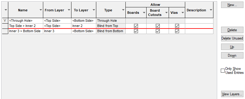
The Layer Spans dialog is used to create and manage defined Layer Spans in the design. A Layer Span defines the possible layers a via can penetrate through the board. Often these are through the board, from the Top to the Bottom Electrical layer.
You can also have Blind vias (where the via goes from the Top or Bottom to an Inner layer), and Buried vias (where the via goes between two Inner layers). These are often more expensive to manufacture, as they require an additional drilling process during board fabrication. You cannot define two Layer Spans which cross over each other, as this is impossible to manufacture.
Shortcuts
Menu: Setup
Default Keys: T
Command: Technology
Locating this option
Available from: Setup menu > Technology option > Layers tab > Layer Spans tab
Using This Dialog
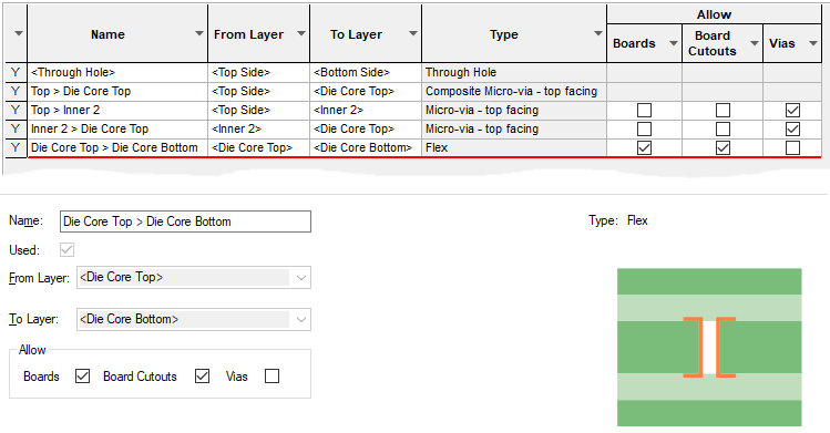
Layer spans are also used for board outlines to create Flexi-Rigid Boards, and for Board Cutout Areas to create Board Cavities.
The in built
The Type field is for information only, and it shows the kind of holes it will produce.
Navigation
The buttons to the right side of the dialog are used to navigate the grid, the general common buttons are detailed on the Technology Navigation page.
The View Layers button takes you to the Layer Stack Preview dialog, which offers a simple view of the layer stack.
Layer Span Edit Pane

First you must provide a unique Name for the Span. Then use the From Layer and To Layer drop down lists to produce a legal span. It is not legal to have two spans which overlap in such a way that they could not be manufactured.
Note: An electrical layer name will be shown in the drop down lists enclosed in angled brackets if the layer has its Can Have Associated Layers flag set. This means a via using the span will have its land available to be drawn or plotted on all layers that are associated with the electrical layer.
To use a micro-via technology you should define the span between same facing layers.
Composite micro-via technology can also be created in this dialog, see below Composite Layer Spans.
Allow (usage)
For non-through hole and non-composite spans, you can define how the span will be used under Allow when the row required is selected.
Selections are available for Boards, Board Cutout Areas (Cavities) and Vias. When using these items in your design, the usage allowed will be assessed (if defined) and the spans restricted to just the allowed type. This will help you refine your selection.
Layer Span Types
Layer spans can be defined for the following via types:
-
Through Hole - a normal hole drilled right through the board.
-
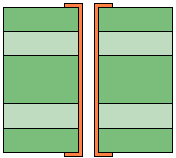
Buried - hole will not show on either side of the finished board and is embedded within the board.
-
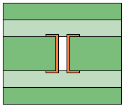
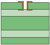
Blind - hole will show only on one outer side of the finished board. Example below shows Top side via.
-
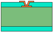
Micro-via - hole is between same facing layers (see Micro-vias). Example below is for a Top Facing Micro-Via.
-
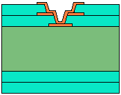
Composite - hole is spanned by a multiple via stack (see Composite Layer Spans below). Example below shows Top Facing Composite Micro-Via.
Composite Layer Spans
A Composite Layer Span is specifically for creating a via stack using by Micro-Vias; that is a stack of vias which together complete the span, this will usually involve a set of micro-vias with the same coincident positions with adjacent layer spans. By being a composite of Micro-Vias, they will move together as a ‘set’.
To create the span, you must first enable the Layers in the Layers dialog as Can Have Associated Layers, and for them to be either Top or Bottom Facing. Composite layers must have the same facing layers.
Secondly, define the normal layer spans that will be used to form the composite. In the example below, we have defined two sets of Micro-vias which span Top to Inner 3 and Inner 3 to Inner 4. A composite will then be created from the two span sets. Two in our example but they can be more if spanning more layers.
With these layer spans defined, you can now define the Composite Span by adding a new span. By selecting the From Layer and To Layer from the lists and using the overlapping spans, the dialog will now offer you the Composite Layer Span selection box. Initially, this will be unselected. To make a composite span, select the check box. This will offer you a list of existing normal spans which when combined together will cover the required composite span. Select the spans required. If defining composite spans for top and bottom layers, there will be more spans to select from.
If there are multiple combinations of normal spans that can be used to create the composite span, press Next to cycle through each set.
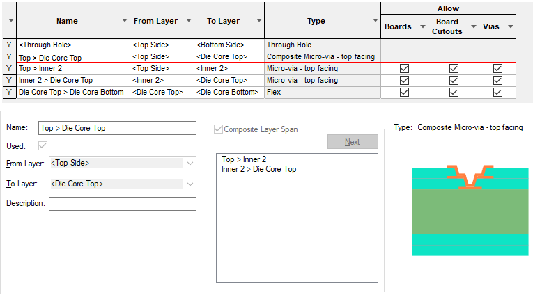
You can change a composite at any time by selecting it in the grid and editing it. You can change it back to a normal span by deselecting the Composite Layer Span check box.
Composite Vias and Net Styles
Once you have a composite span defined, you can then define the Pad Style to use for each part of the span. Only nets which have these styles defined using the Net Styles system can use the composite span to create stacked vias.
Layer Spans and the Routing Options
Manual and Automatic routing will automatically select the most appropriate Layer Span to use for a given via defined.
Related Topics
Technology Overview | Board Cavities | Flexi-Rigid Boards | Technology - Layers | Technology - Layer Stack Preview | Micro-vias | Routing | Insert Via | insert Track | Using Dialog Grids