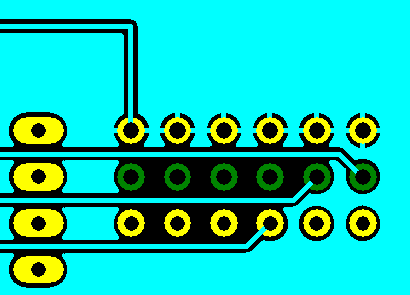
Pour Copper is used to flood unrouted areas of a PCB layout with copper usually connected to a nominated signal - typically Ground (GND) or VCC. This facility will then create voids around unconnected tracks, components, pads, etc.
Normally, you would define an area to be poured using a Template. It is also possible to pour a copper shape directly. This is useful for moulding a piece of copper around some other items. However, once a copper shape has been poured, the original shape is lost. Using a template, the template still defines the original area, and it can be poured again. If you pour a copper shape, no thermal pads are added.
Shortcuts
Default Keys: None
Default Menu: Utilities
Command: Pour Copper
Locating this option
Available from: Utilities menu > Pour Copper option
How To Use Pour Copper
Before the Pour Copper operation may begin, the area that bounds the copper area should be defined by a Template.
Creating a Template
From the Insert menu, select Insert Template then select: Polygon, Rectangle, or Circle.
Once the appropriate shape type is selected then the shape may be created within the area of the board outline that is to enclose the required copper area, or this may be outside the board outline if copper is to fill the complete board area.
Attach Template to a Net
Once created, the Template may be selected by Select or Select Edit then right-hand mouse key and from the menu select Add to Net. The ‘Add to Net’ menu opens where the relevant net and net class may be selected.
Once the Template is created and attached to a Net you may proceed to the Pour Copper stage.
How To Pour Copper
-
Select the Template using a single mouse click. From the Utilities menu select Pour Copper;
or as a quicker method:
-
Select the Template using a single mouse click, right-hand mouse and select Pour Copper from the context menu.
The Template area will fill with copper leaving voids around unconnected items.
To create copper hatching after pouring see Hatch help file. To set Hatching as a default parameter each time copper pour is carried out see the Change Pour Copper Parameters section below.
How To Change The Order Of Pouring
Sometimes templates of different signals on the same layer may overlap ( or be wholly inside ). In these circumstances you may want to specify which template has the priority, i.e is poured first. Use the Ordered Template Pour option to change the order in which templates are poured.
To Change Pour Copper Parameters
The parameters for the Pour Copper option are defined by creating Copper Pour Rules for your nets or net classes. A specific rule can also be defined for a net attribute and assigned directly to a template by adding the attribute to the template. Within a Copper Pour Rule you may define the following:
You may determine the Minimum Island Size of individual areas of copper within the design in thou sq. If a given area of copper falls below this size then copper will not be placed.
On Remove Isolated Islands you may request that isolated islands of copper that cannot be tied to a Net be automatically removed. Otherwise, there is an option to highlight the isolated islands.
On Hatched and Style you will determine if the copper flood is to have a hatched appearance and the style of hatch required.
How Pour Copper Deals With Thermal Pads
The way the Pour Copper option connects the copper flooded area to the thermal pads on the nominated net is defined by creating Thermal Rules for your nets or net classes. A thermal rule can also be defined for a net attribute and assigned directly to a template by adding the attribute to the template.
In the thermal rules you can set the thermal relief Isolation Gap, Spoke Width, First Spoke Angle, and the number of spokes.
Any given pad can override the default thermal rule and be isolated or completely connected to the copper (edited through the Power Plane Connection control on the appropriate property page).
The Result
The area will flood with copper leaving an isolation void around tracks, pad, vias, connectors, etc. plus a connection through Thermal Pads to the nominated signal.
You can edit and delete copper generated by Copper Pour but by using a suitable Line Style (taken from the Template), Minimum Island Size and Remove Isolated Islands defined in Pour Rules, you can produce a clean result first time.
You may sometimes get the message No Connected Copper Areas when no copper has been generated. This is usually because you have used the Remove Isolated Islands option, and none of the resulting copper could reach a pad or other copper connected to the net.

Latch Mode
Pour Copper can be used in Latched Mode allowing copper to be poured simply by picking the template. All templates can be poured using the ALL option from the shortcut menu.
Related Topics
Clear Template | Hatch | Insert Circle | Insert Polygon | Insert Rectangle | Insert Template | Ordered Template Pour | Pour Copper - Locked Items Dialog | Technology - Copper Pour Rules | Technology - Thermal Rules | Options - Templates