Use to change the layer that the selected items, or item being edited, is on.
Details of available layers are defined in the Layers section of the design’s technology data.
There is also a Swap Layer command that allows you to pick items to flip them to their associated layer on the other side of the PCB board.
A set of commands are also available to change the layer of the selected item directly to an electrical layer. Use Change To Layer 1 to change to the top electrical layer, Change To Layer 2 to change to the next electrical layer and so on. These commands are only available if the selected item can exist on an electrical layer. If you want to use these commands regularly, you can associate them with shortcut keys using customise. For example you could assign layers 1 to 10 to keys 1 to 10, and layers 11 to 20 to keys shift + 1 to shift + 10.
Shortcuts
Default Keys: L
Default Menu: None
Command: Change Layer
Locating this option
Available from: Context menu > Change Layer option
How To Change Layer
Use the following procedure to simply change an item’s layer using Change Layer. An alternative way to do this is to use the Properties option.
-
If the mode you are currently using does not have Change Layer on it’s shortcut menu (Edit Track, Edit Shape, Move etc. do) then exit this mode to get back into Select Mode or Edit Mode.
-
If not already selected (or being edited), select an item, or multiple items, and right click the mouse to use the Change Layer option from the shortcut menu.
-
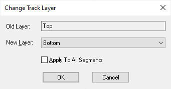
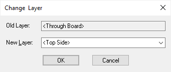
One of the following will appear depending on if any of the items is a track. Note: if the items are vias the Change Layer Span option will be used. If the item is a track that is part of a broadside coupled differential pair then you will be presented with a dialog to change both layers (see below).


-
The current layer used for the item is shown in the Old Layer box. If multiple items were selected on different layers, [Different] will be shown. The New Layer box will be setup if possible with the corresponding layer ( same Layer Type and Class) on the other side of the board. This makes it simple to swap layers from one side of the board to the other.
If this option is being used whilst in Edit Track, the New Layer will be set to the layer previous to the last layer change. This makes it easy to toggle between two electrical layers whilst laying down tracks.
Choose the required layer for the item from the list of appropriate layers defined in the design. This list will be restricted to layers of the correct type for the selected items. The details of these layers can be found in the design’s layer technology data.
-
If editing a track, use Apply To All Segments to apply the new layer to all segments of the selected tracks. Leave unchecked to only apply this change to the selected segments.
-
Press OK to use the chosen layer for the selected item. The item will swap to the new layer and any items attached to it will be ‘repaired’ to make sure they reach the item on the new layer.
For example, if a pad that has a track connected to it is swapped from the top to the bottom of the board, the attached track segment is also swapped and a Via will be introduced at the end of this segment to reach the other segments of the track.
Similarly, track segments that change layer will have vias added or removed from their start and end positions to ensure there are no extra unnecessary vias and that there are no breaks in the track’s signal flow. If the design’s Layer Span data includes buried or blind vias then a via with the best fit layer span will be used when a track segment changes layer.
Broadside Differential Pairs
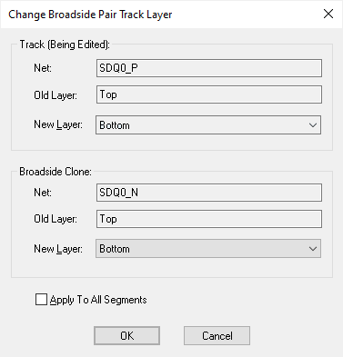
If the track being edited is part of a broadside coupled differential pair its paired clone track must be on a different layer. In this case the track layer dialog is shown with both layers as follows:

At the same time as changing the track layer, you can change the layer that the broadside clone track will be on. If you are currently adding paired segments you cannot set the two layers the same, but if you are not currently pairing, for example if you are mirroring the tracks, the layers can be the same so that you can connect both tracks to surface mount pads on the top or bottom side.
Sometimes, this dialog will be presented for you to just provide the layer for the broadside clone track, for example when you are using Start Differential Pairing and the system just needs to know what layer to put the clone track on.
Boards, Areas and Mounting Holes
In order to support Flexi-Rigid boards, using Change Layer on board outlines, areas and mounting holes in a PCB design will also include layer spans at the bottom of the list of layers you can change to.
Components
You can perform Change Layer on an Embedded Component, this will allow you to change the layer of the component to any other layer that has Allow Buried Component enabled and has suitable non-electrical essential layers.
Normal components can also be placed on inner layers using Change Layer when placing them on to the flexible part of Flexi-Rigid Boards or placing them into Cavities in a board. This means the components are not buried into the board stack, but also do not sit on the outer most layers. Use Change Layer to place the component on any layer that has Allow Normal Component enabled. If the component is not surface mounted you will be presented instead with the Change Layer Span dialog to choose a suitable span that represents the required span for its through-hole pads and mounting holes. So if a through-hole component is being placed in a cavity in the top side of the board, make sure the layer you are placing it on is allowed to have normal components on it and make sure there is a layer span from that layer to the bottom side of the board.
Note: Change Layer can only be used on single components.
Related Topics
Edit Mode | Edit Track | Embedded Components | Board Cavities | Flexi-Rigid Boards | Layers Overview | Properties | Select Mode | Swap Layer | Technology - Layers | Technology - Layer Spans