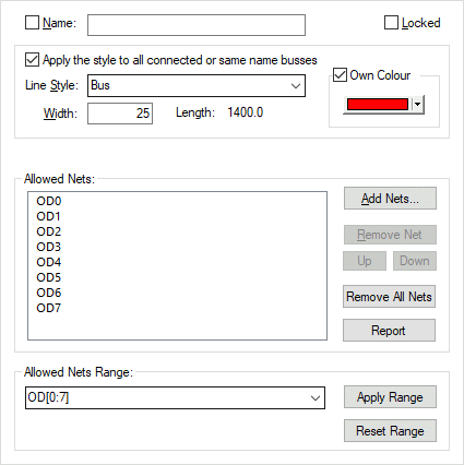
This properties tab is available when using the properties option on one or more selected bus segment(s). Use it to change the selected bus line style and allowed nets.
Shortcuts
Default Keys: I or Alt+Enter
Default Menu: Edit
Command: Properties
Locating this option
Available from: Edit menu > Properties option
Available from: Context menu > Properties option
Available from: Shortcut key > I
Using The Bus Properties Dialog
Select a bus segment (or several) and enter properties. Choose the Bus tab and the following dialog is shown:

Name
Enter the name for the bus. You can only name a closed bus. All closed busses with the same name are forced to always contain the same set of allowed net names. This name can used in the Find and Change Bus operations.
Check the box if the name is to be visible. The displayed name will use the ‘Item Name’ attribute and will take its style from the bus defaults in the Design Settings dialog. Note that it will only be visible on screen if the ‘Item Name’ attribute is also set to displayed in the Colours Dialog.
Locked
Use this to lock the bus from future editing. Once the bus is in its final position, lock it to avoid accidentally altering it.
Apply the style to all connected or same name busses
The check box Apply the style to all connected or same name busses will cause all the associated busses to take the same Line Style and Own Colour options. The default value for this check box is defined in the Bus Defaults dialog.
Line Style
Choose the required line style for the bus from the list of line styles already defined in the design. These can be altered using the Technology option from the setup menu. The width for the selected style will be shown in the edit box.
If you do not know the name of the style then type the required line width in the width edit box. The style that matches the typed line width will be selected from the list. If no line style in the design matches the typed width then the line style name box will be left blank. Type the new name for the line style, or leave blank for the system to assign a default name for you.
Own Colour
Busses can be drawn in their own colour, this colour is used irrespective of the colour defined in the Colours Dialog.
Allowed Nets
Listed here are the net names that represent the signals that the bus can carry. If any net names are listed the bus is Closed, so only the listed nets can be connected to the bus. If there are no names listed the bus is Open, so any net can be connected to it.
Add Nets…
Use this to add some net names to the closed bus. It displays the Add Net To Bus dialog that allows you to select from net names already in the design, or add your own new net names. If the bus was open (i.e no names listed), and it has nets already connected to it then you will be asked to add these nets to the list automatically. If the bus has default named nets connected to it (e.g. N0001) you cannot turn it into a closed bus.
Remove Net
Use this to remove the selected net name from the Allowed Nets list. You cannot remove names of nets that are already physically connected to the bus or any other bus of the same name.
Remove All Nets
Use this to turn a closed bus into an open bus by removing all of the net names from the Allowed Nets list.
Report
Produces a report showing the name of the bus and a list of the nets.
Allowed Nets Range
This initially displays the list of Allowed Nets in range format. This is the string you would see if you displayed the net name on the bus.
You can use this to type in the required closed bus nets directly in range format, or select from a list of name ranges used elsewhere in the design.
If the text is changed the Apply Range and Reset Range buttons are available. Apply Range allows you to apply the changed string to the Allowed Nets list. Reset Range resets the string to match the current names in the Allowed Nets list.
Related Topics
Add Net To Bus | Bus Attributes Tab | Bus Terminal Properties | Connecting To Bus | Insert Bus | Bus Defaults | Properties Overview | Segment Tab | Technology