Import Gerber is used for importing Gerber Files. The drawn lines are converted into documentation shapes or tracks, and flashes into pads. These can then be edited, moved, etc. because they become part of the design. As Gerber is widely supported by drawing packages, this is a convenient way to import shapes (such as the board outline) from an alien system.
This option is not a substitute for a Gerber viewer and it is recommended that you obtain one of the commercially available Gerber viewers to check you designs before manufacture.
The import process attempts to rebuild the lines into shapes (or tracks on an electrical layer). There is no information in the Gerber as to how to interpret the lines, so shapes which have been filled using hatch lines may result in a large number of shapes which will take a long time to import.
If you choose to import onto an electrical layer, then the lines are interpreted as tracks and the import process will attempt to rebuild the connectivity. This should only be attempted on Gerber files which have sensible track patterns (and not hatch filled areas), otherwise the import process may take a very long time and result in thousands of tracks which do not serve any useful purpose.
Note, thermal pads and user defined pad shapes will be imported as circular pads.
Shortcuts
Default Keys: None
Default Menu: File
Command: Import Design Data
Locating this option
Available from: File menu > Import Design Data > choose Gerber Artwork *.gbr
Using The Dialog
Import Design Data
You must have a PCB, Schematic or Footprint design open. Select Import Design Data from the File menu. You can then browse for the Gerber file that you want to import. You will then be presented with the following dialog:
Import using drag and drop
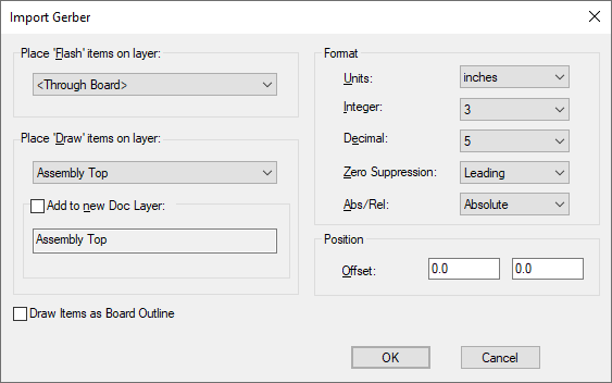
As an alternative to using the Import Design Data dialog, simply drag and drop your Gerber file from the Explorer dialog straight on top of your PCB and the Import Gerber dialog will be displayed:
This option performs a initial pass of the selected file to determine the units format and the required offset. These will be initialised in the dialog, you may want to review them before importing.

Place ‘Flash’ items on layer: This will interpret any flashes in the Gerber file to be imported as pads
in the design. The Layer chosen should be representative of the Gerber file, e.g. if a through hole design
select
Place ‘Draw’ items on layer: The layer drawn items are imported onto. If the layer is electrical Open shapes are interpreted as tracks. Filled shape are imported as Copper areas.
Add to new Doc layer: This allows a new documentation layer to be created on-the-fly if it does not already exist in the design. This layer could then be used as an overlay for Component placement for example.
Draw Item as Board Outline: Board outline shapes in Pulsonix are not related to a specific layer. This selection enables you to add the contents of a Gerber file to a special Board Outline item.
Format: These entries are used to define the format of the in coming Gerber file if in RS-274-D format. If the parameters are unknown, you should either contact the person who generated the files in the first place, or use the default settings. If the file is in RS-274-X format, these parameters are defined in the file itself and hence, the settings are initialised to the values in the file.
Position: An Offset can be defined for which to move the imported Gerber files to. Using this offset, you can position the design relative to any existing design information.
Gerber X2 Format
If the Gerber file contains X2 format commands (AperFunction, FileFunction or Part), an additional message will be displayed on the dialog to inform you that these commands have been detected but will not currently be processed. For more information about Gerber X2 restrictions click here