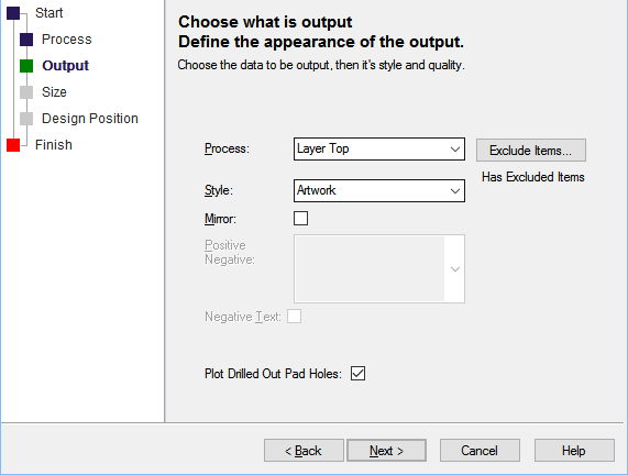
The Output page is used to define data to be output, and the style of the plot generated.
Using the Wizard
Process
You must now use the Process drop down list to specify what is to be output, this is usually a layer (or for schematics, a page). For a panel design you can also choose the Panel process to create a plot for the special panel shapes (see Panel Designs below).
If your design uses variants, then you can specify which variant is being plotted.
Plot Unfitted, if checked will cause unfitted components to be plotted.
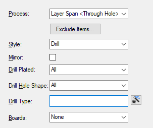
You can specify the Style of output. The normal choice would be Artwork, but for test plots you may wish to use Outline which does not plot the fill in filled shapes. The style for a Layer Span is fixed to Drill for NC Drill output and Drill Drawing for other devices.
You can also specify if the plot is mirrored, the plot will be mirrored within it’s own space and does not affect the size, rotation or position on the output device.
Excluding Items from the plot
You can also choose to exclude certain items from the plot by pressing the Exclude Items button. See Exclude Items dialog for more information.
Style
The Style field defines the quality to be output. Normally, the style would be Artwork, but for test plots if may be desirable to use to use Outline which does not plot the fill in filled shapes. Style can only be edited through this Plot Wizard.
Mirror
Mirror defines if the output is to be mirrored. You might use this for the bottom side of the board when plotting a Top Electrical layer for example.
Positive Negative
For power plane layers you can also specify how this layer is to be plotted. The options are:
Plane Style : is only relevant to power plane layers. It defines how the power plane is to be plotted. The Plane Style can only be edited through the Plot Wizard. The Plane Style can be:
- Negative (only plot gaps) : Only plots the oversized design items, to give a negative artwork.
- Positive (only plot items) : Plots the power plane as though it were a normal positive electrical layer. This could be combined with a photo-reversed Negative plot to produce a full positive plot.
- Negative (plot isolation) : Plots the gaps between copper items. This is a full negative plot. It is the equivalent of combining a Negative (only plot gaps) plot with a photo-reversed Positive (only plot items) plot.
- Positive (plane & items) : Plots a full positive output of all the copper on the power plane. It is the equivalent of combining a photo-reversed Negative (only plot gaps) plot with a Positive (only plot items) plot.
Negative Text on power planes gives text which is cut out of the plane, this allows a negative plot to contain text without having to combine with a positive. Negative Text is not plotted on a positive plot. The default is Positive Text, which in a negative plot, produces a gap in the plane large enough for the positive text to be plotted. Note that this check box only applies to the current plot.
| Positive Text combined with gap in negative plane | Negative Text |
 |  |
Using the Allow Break Around Pads feature
Break around pads is defined on the layer class, to break shapes around pads (on Silkscreen layers, for example). Unchecking the Allow Break Around Pads option will prevent shape breaking around pads for this plot. Breaking around text is unaffected.
Plot Drilled Out Pad Holes
If the current plot is plotting holes in pads, normally this will be a hole in the copper land. If the land is smaller than the hole, then the land would be drilled out completely, so nothing will be output. However, with this option check, the drill hole is output as a copper shape, the same size as the drill hole. This might be useful, if you are hand drilling the holes and need a marker. As this is a specialised use, this option is off by default.
Drill Outputs
To get NC Drill data, you should output to Excellon and select the span to Process, the style will default to Drill.
To output milling data for the board profile, select Excellon output and select the layer showing the profile data (all shapes on this layer will be output), the style will default to Outline. If the board outline defines the shape to be profiled, remember to make board visible in the layer class used by the layer. It is also possible to output the milling data in Gerber format by selecting a layer span and the Drill plot style. This could be particularly useful when using the Gerber X2 format.
A Drill Drawing, showing the drill symbol and identifier for each drill hole is created by selecting an output other than Excellon and selecting the layer span to output.
For Drill and Drill Drawing outputs, you can specify if you want All drills, or just Plated or Unplated drills.
Similarly, for Drill and Drill Drawing outputs, you can specify if you want All drills, or just Round or Non Round drills (slotted pads). Obviously, Non Round holes cannot be drilled, and are milled, which means that the Excellon output will contain shape outline data. Select None to prevent any drill holes being output.
If you need more control of the drill drawing output, you can create a Drill Drawing layer where you can see the drill drawing within the design.
You can also choose to include the board outline and board cutouts using the options in the Board: drop down. Select All Boards (including Area Board Cutouts), Outlines Only (does not include Area Board Cutouts) or Cutouts Only (only Area Board Cutouts). Area Board Cutouts can be plated or non-plated, and these are selected using the Drill Plated above. Select None to prevent any Board outlines being output.
Slotted Pads
An additional mention here is for exporting non-round holes such as those used in slotted pads. Some manufacturers require zero size drills so that the ‘corners’ of slots can be milled out more accurately using the smallest drill/ laser available to get into the ‘square’ edges. Where a non-round drill shape has been specified and the shape cannot be uniformly milled, a bullet, for example, the drill report exported will contain a zero size and a quantity. Your manufacturer should be made aware of this and how to process it. Alternatively, process these special pads to a unique non-round file for processing separately.
Drill Type
The Drill Type of special drills can be matched using a wildcard string so they can be processed separately.
Panel Designs
The Plot Contents Of Each PCB Design check box is only shown if you are producing a plot for a Panel Design. Check the box to specify that each PCB item in the panel will be replaced by the full contents of it’s PCB design file. Leave it unchecked if you are just producing a quick check panel plot and only want to output the items you see in the PCB instances in the panel design.
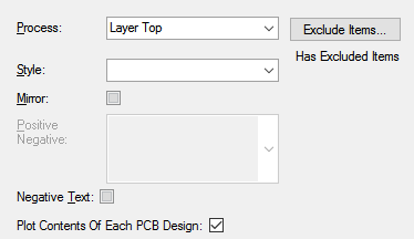
To create a plot for the special panel shapes, select the Panel process. You will then be able to choose which type of panel shape you wish to output for this plot. For example you could select output to Excellon (on the previous page) and select Panel Tab-Rout to produce milling data for the tab-routs in the panel.
Plot Wizard Pages
Start | Process | Output | Size | Position | Finish
Related Topics
CAM Plots | Output Device Settings | Exclude Items | Drill Size Table | Using Wizards