Locating this option
Available from: Setup menu > Colours > highlights tab
Using the Highlight Colours Tab

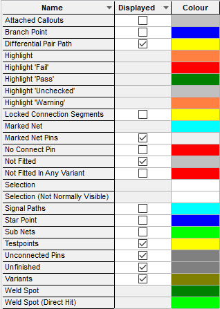
This tab has a list of highlights which override the colours of various item types under specific circumstances. Making these highlights not displayed does not turn off the items, it just makes them revert to their original colour.
-
Attached Callouts defines the colour of Callouts which are attached.
-
Branch Point defines the colour of a Branch Point documentation symbol.
-
Differential Pair Path defines the colour of the pad to pad path connections in a Differential Pair. Note, it is possible to override this colour on an individual Differential Pair. when defining it in the Technology dialog.
-
Highlight defines the colour of highlighted items. Items may be temporarily highlighted by the various find options and during some other operations.
-
Highlight ‘Fail’, ‘Pass’, ‘Unchecked’ and ‘Warning’ define the colours used to indicating the database status of a component when it has been Checked Against the Database.
-
Locked Connection Segments defines the colour of connection segments that have been locked.
-
Marked Net defines the colour of the marked net. (Not available in schematic symbols).
-
Marked Net Pins defines the visibility of pins on the marked net. Use this to show pins on the marked net when pins have been switched off in the main colours dialog. (Not available in schematic symbols).
-
No Connect Pins when enabled, causes the name of the pin type to be substituted in to the Net Name attribute for No Connect pins. Whilst enabled, a Net Name attribute position will be added to a pin if you make it No Connect. Additionally, the context menu option “Show No Connect” will be available when Right Clicking a pin of type No Connect. It will be drawn in the highlight colour. This will work on a Component Pin or Block Port.
-
Not Fitted defines the colour of all the components or gates that are not fitted in the current design variant. (Not available in schematic symbols)
-
Selection defines the colour of items which have been selected, usually using Select Mode.
-
Selection (Not Normally Visible) defines the colour of items which have been selected, but are not normally visible. For example, selecting a connected pin.
-
Signal Paths defines the general colour of Signal Paths. A Signal Path can have it’s own colour, which will override this.
-
Star Point defines the colour of Star Point documentation symbols.
-
Sub Nets defines the general colour of Sub Nets. A Sub Net can have it’s own colour, which will override this.
-
Testpoints defines the colour of Testpoints. (Not available in symbols)
-
Unconnected Pins defines the colour of all unconnected pins. No Connect pins are not highlighted. (Not available in schematic symbols)
-
Unfinished defines the colour of all unfinished connections. A connection is unfinished if it is on a net that has less than two component pins, or it is dangling (no item at its end) and has no visible net name at either end, or it is dangling and connected to a bus at the other end.
If you find connections are unexpectedly marked as unfinished, try selecting the open end of the connection and doing Show Net Name to display the net name at that end, these problems are generally caused when a net name appears to belong to the connection but is actually attached to a pin elsewhere on the net.
-
Variants defines the colour of all variant components or gates that are not fitted in at least one of the variants defined in the design. (Not available in schematic symbols)
-
Weld Spot defines the colour of the spots that are drawn during move to show where Auto Weld can be performed. (Not available in schematic symbols).
-
Weld Spot (Direct Hit) defines the colour when the weld would join two items that are directly over each other. (Not available in schematic symbols).
Related Topics
Colours - Overview | Marked net | Online DRC | Insert Test Points | Electrical Rules Check