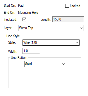
This dialog is displayed when the Properties option is chosen with a PCB or Footprint wire selected.
It shows and allows you to modify properties for the selected wire.
Shortcuts
Default Keys: I or Alt+Enter
Default Menu: Edit
Command: Properties
Locating this option
Available from: Edit menu > Properties option
Available from: Context menu > Properties option
Available from: Shortcut key > I
Using the Wire Properties Dialog
As well as the Wire properties, there are additional tabs showing the associated Net and Net Attribute properties.

The Start On and End On fields show the items the wire start and end on.
Locked shows if the wire is locked, in which case all other dialog items will not be editable.
The Insulated check box shows if the wire is marked as insulated. Insulated wires are allowed to be crossed. Non insulated wires can be checked for crossing using the Design Rule Check tool. Insulated wires can be reported separately using the Report Maker.
The Length field shows the length of the wire.
The Layer field shows the wire layer on which the wire appears. These are special layers that are above and below the board. To change, select an alternative layer from the dropdown list. Changing the layer of the selected wires may introduce vias.
The Line Style fields show the name and width of the line style used on the selected wires. To change, either choose an existing line style from the Style dropdown list or use the edit boxes to create a new style.