This Properties option is available on a selected Star Point Symbol. Use it to change the star point name or the symbol used to represent the star point.
This star point would have been added to your design using the Insert Star Point option. Generally speaking, a star point pad would be the same size (or smaller) as the tracks attached to it and would be on the same layer as the tracks as a surface mounted item. These Properties can be changed as required though using Pad Properties.
Shortcuts
Default Keys: I or Alt+Enter
Default Menu: Edit
Command: Properties
Locating this option
Available from: Edit menu > Properties option
Available from: Context menu > Properties option
Available from: Shortcut key > I
Using The Star Point Symbol Properties Dialog
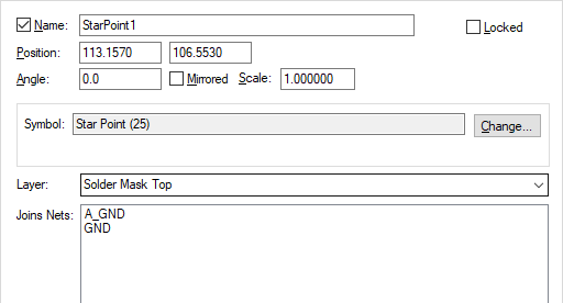
Select a documentation symbol star point (or several) and enter properties. Choose the Star Point Symbol tab and the following dialog is shown:

Name is the name of the star point, this must be a unique for any star points in the design. You can display the Star Point Name by checking the box next to the name.
Standard status selections and check boxes are available to manipulate the star point; Locked or Unlocked, X, Y Position, Angle, Mirrored status and Scale.
The coordinates of the symbol can be changed using the Position edit controls.
The Lock, Angle, Mirrored State and Scale of a star point would not normally be changed, but if you want to see how to adjust these on a star point refer to the Documentation Symbol Properties dialog.
Symbol is the name of the documentation symbol used for the star point. This will be defined as a star point type in the doc symbol library. Use Change if you want to change symbol to another one from either the same library or another documentation symbol library.
The Layer box will be displayed in a PCB design and allows you to change the layer of the star point name if displayed. You can display the name on any non-electrical layer.
Joins Net, lists the nets joined by the star point. This is for information only and cannot be changed here.
To change the Layer and Pad style in PCB, use the Pad Properties tab.
Schematic star Point Doc Symbol dialog variants
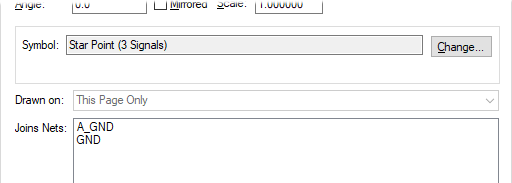
When viewing star point Properties in a Schematic design, there will be an extra box to show you which page the symbol is Drawn On. Individual star points can only be drawn on the current page (This Page Only).

Related Topics
Attributes Tab | Insert Star Point | Star Point Defaults | Properties Overview | Properties Star Point | Properties Pad