You can insert multiple copies of Components, Connector Pins, Mounting Holes, Pads or Vias using the Insert Multiple Items dialog to define how many items in each direction and the gap between them. You can also use this option within the Panel Editor to initially place or rearrange multiple boards.
Alternatively, if you already have one of these items in the design, select it and use the Replicate option to insert multiple copies.
Shortcuts
Default Keys: None
Default Menu: context menu
Command: Insert Multiple Items
Locating this option
Available from: context menu > Insert Multiple Items option
How To Insert Multiple Items
First enter the Insert Component, Insert Connector Pin, Insert Mounting Hole, Insert Pad or Insert Via option. You can also use this option in Insert Panel PCB Design and within the Panel Editor.
Choose the details of the item that you wish to add and whilst placing it right click to use the Insert Multiple Items option from the shortcut menu.
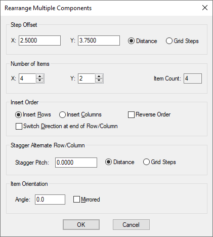
This dialog will be displayed:

Step Offset
The Step Offset defines the distance each item is offset from the previous one. Choose to define the offsets as a Distance using the current design units, or as a number of Grid Steps, using the grid used by the current insert mode. There are separate values for X and Y and they may be negative to step in the reverse direction.
Number of Items
Define the number of items in the X & Y directions. These numbers include the original as the first item (so they start from 1).
If the item being added is a schematic gate or connector pin, check the All Items In Component box to insert all remaining gates or pins in the current component being added. The count of unplaced items remaining in the component will be shown in an edit box. Checking this option will change the item counts to have a row or column with the correct number.
Insert Order
Use this to define the order that the items are added. First select Insert Rows or Insert Columns to specify the items are added in rows or columns, and check the Switch Direction box to specify that the next row is started above the end of the previous row, or leave unchecked for each row to be added in the same direction.
You can check the Reverse Order box to make the offsets go the other way. This is easier and more obvious than making the offsets negative.
Stagger Pitch
Enter a value here if you want alternate rows (or columns) to have their start position offset by an additional pitch. This will create a staggered pattern that is sometimes used for pad arrays. Choose to define the pitch as a Distance using the current design units, or as a number of Grid Steps, using the grid used by the current insert mode.
Item Orientation
If the items being added have an angle and can be mirrored, use the Angle and Mirror boxes to set the orientation of each individual item.
Placing the items
Press OK to add the multiple items. They will all be dynamically displayed on the cursor for you to click in the required position. Use Insert Multiple Items again to alter the item counts or gaps between them whilst placing the items. Set the counts to 1 to go back to adding a single item.
You may already have the components in your design, for example if transferred from a schematic design to a PCB design, and want to arrange them using the multiple items method. This can be done by selecting them and using the Rearrange Multiple Items option from the shortcut menu.
A quicker method to add multiple items
Whilst selecting the Insert Pad, Insert Mounting Hole or Insert Via tools, you can hold the shift key down to go straight into the Insert Multiple Items dialog.
Related Topics
Insert Component | Insert Mounting Hole | Insert Pad | Insert Via | Rearrange Multiple Items | Replicate | Insert Panel PCB Design | Panel Editor