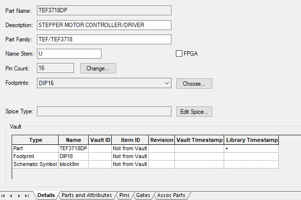
This page is used to define the general details for the part. It provides access to the information specified on the New Part dialog and when editing an existing part. In addition to general part details such as Description, Part Family and Name Stem, it also allows you to specify the footprints used by the part and the Spice Type used for Spice simulation.
Locating this option
Available from: Library Manager option > Edit button > Parts tab > Details page
How to Use This Page
To change the text items on this page, simply click on the item you wish to change and use the edit command available. Items greyed out cannot be edited.

Part Name
Part Name is fixed in this dialog. This is as defined when using New Part. To change this name, use the Copy or Move option from the Parts Editor dialog. you cannot do it from this current dialog.
Description
This field is used to provide a readable description of the part. This appears in various dialogs, such as Insert Component and Report Maker options. It can also be used in reports extracted using the Report Maker option. It can contain attribute substitutions from the part. For example: *Resistor *. A part description field is not mandatory but optional.
Part Family
The Part Family field is used as a way of linking together related parts for easier browsing. It is not mandatory but optional.
Name Stem
The Name Stem field specifies the text to be used for the first part of the component name when this part is used in a design, for example U, R, C, (like U11, R1, C9) etc.
FPGA
The FPGA check box indicates that this Part is an FPGA device. It will become automatically checked when the Import Pin Data option is used to import FPGA pin information from an external file such as the Altera .pin file or the Xilinx .pad file. Alternatively, it can be explicitly checked if FPGA information for a part is being constructed manually, for example, using copy and paste from a third party source. For more information see FPGA Support in Pulsonix.
Pin Count
The Pin Count field specifies the number of pins on the component itself, and hence the number of pads on the PCB footprint. To change the number of pins in the part, click the Change button to open the Edit Pin Count dialog. Changing this will change the footprint list and may create errors on the Gates page.
Note that there is also a Part Pin Count which shows the pin count the part will report for search purposes. This will normally be equal to the Pin Count, but could be less if you are using Ancillary Pads.
Pin Count - Special Conditions
When using the special Pin Types of Ancillary Pad or Mounting Hole the pad number reported will be different to that defined on the footprint. In this situation, the Pin Count changes and the dialog is updated.

The Pad Count changes to reflect the actual number of pads defined. An additional Part Pin Count now displays the count, excluding any pins marked as one of these special types.
Footprints
To change the list of footprints defined for this part, press the Choose… button to open the Footprints dialog. When using the list, the first footprint shown is the default one used when you use Insert component in the design. The order can be defined from the Choose Footprints dialog.
Spice Type
Use the Edit Spice button access the Define Spice Type dialog. This is used to define the type of Spice device that the selected Part represents for Spice simulation.
Part Editor tabs
Each tab of the Part Editor is described on a separate page:
- Details - this page. Part details, footprints, pin count, Spice Types
- Parts and Attributes - part names and part attributes
- Pins - PCB footprint pin names, pin remapping, assigned net names, pin types, pin networks, pin attributes
- Gates - Schematic symbols, logic names, swap groups
- Associated Parts - parts associated with the main part which should also appear in a parts list
Connectors
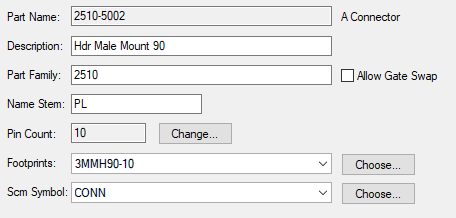
For a Connector, the Scm Symbol is selected on this page, and there is no Gates page. You can specify alternate symbols if you wish.
For Connector Parts, there is a check box to Allow Gate Swap. This allows connector pins to be swapped between equivalent connectors using Swap Gates. They can only be swapped with equivalent pins which have the same pin swap value defined.

Vault
If the Vault is in use, the Vault section will show vault details for the part and its footprint and schematic symbol.

Related Topics
New Part | Parts Editor | Part Family | Change Pin Count| Choose Footprints | Define Spice Type | Parts and Attributes | Pins | Technology - Pin Types | Gates | Associated Parts