This option allows you to add multiple parallel tracks at the same time representing groups of signals such as memory routing, differential pairs and busses that need to be routed together.
Shortcuts
Default Keys: None
Default Menu: Insert
Command: Insert Bus Route
Locating this option
Available from: Insert menu > Insert Bus Route option
How To Use Insert Bus Route
This section will guide you through the interactive bus routing tool.
-
From the Insert menu, select Bus Route, or using one of the shortcuts available. This takes you into Insert Bus Route Mode.
-
If a single track is pre-selected, then the width and layer are taken from the selected segment to use when adding the tracks for the bus route in this session. This is the same as changing style prior to adding the new bus route now. Also, if a new net is created for any new tracks, it will use the net class from the pre-selected track. The pre-selected track will remain selected until the bus route is added.
-
Alternatively, if a set of pads, vias, parallel segments at the end of some tracks, or a set of unrouted connections are pre-selected these will define the set of nets to be routed together in the bus route.
-
Before you select items to start the bus route from, you can right click the mouse to use the context menu to do the following:
-
Change Layer - Use this to set the layer that you wish the tracks to be on. This layer is used if the picked items to start from reach it, otherwise the layer the start items are on will be used. You can also use Next Layer and Previous Layer to step through the different layers. If Draw Current Layer On Top in the Display Options is set, the picture will be redrawn to show all items on this layer on top.
-
Change Style - Use to change the width of the track to a specified value. This value will be used even if the picked items are already on a net and have a style associated with a net class. The new style is shown on the status bar.
-
Use Default Track Style - Use to change the width of the tracks back to using the default style. The style on the status bar is cleared to indicate that the track style will be defaulted as follows:
If each track has track styles defined through the Net Styles dialog, the default track style is the nominal width on this net style entry, otherwise the default track style defined in design settings will be used.
-
Change Number of Tracks - This option is available if you do not have any items selected to start the bus route from. It is used to specify how many tracks you want in a bus route containing new nets. The number of tracks that will be added is displayed in the status bar at the bottom of the screen.
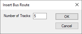
Use this if you are early in the design cycle and just want to reserve space for a bus route using default track to track spacings whilst placing key components. It can be removed or altered to contain the correct nets later on.
-
Define Bus Route Nets - If it is difficult to pick items to define the nets you want in the bus route, use this option to choose the required nets from a list of net names in the design. If you have selected Use Multiple Layers then this option changes to Define Bus Route Nets and Layers with an addition Layers column from where to define layers.
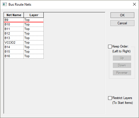
Use the Choose Nets section to select the required nets, and press the Add To List button to add them to the bus route. To help with this you can choose a bus name or a range of sequential net names from the design. Bus names will only be available in the PCB design if you have used Synchronise Designs to update the PCB from the schematic.
A net name can be removed by selecting it in the list and pressing the Remove Net button, or you can clear the whole list by using the Remove All Nets button. If the order of the names is important check the Keep Order box and use the Up, Down and Reverse buttons to rearrange the net names in the list. The name at the top of the list will be on the left as you add the bus route to the design. Uncheck the Keep Order box if you want order defined by the positional order of the pads, vias or track ends that you are using to start the bus from.
When you exit the dialog connections will be drawn to the nearest nodes on the chosen nets, ready for you to start the bus route.
-
Pick Connections - This switch toggles the ability to pick connections. Picking a connection defines the start and end point that the bus route will be connected to for this net. Sometimes there are too many connections in the way and disabling picking aids selection of pads to start the bus route from and picking of the place to start adding the bus route segments. Using this switch is the same as using the pick connections check box in the layers bar.
-
Route Connections At Bus Start - Switch this on if you want the dynamic unrouted connections at the start of the bus route to be converted to tracks as soon as you select the position to start the bus route from. A simple routing algorithm will be used that does not allow layer changes or complicated patterns to be created. If the connections cannot be routed simply, they will be left unrouted for you to complete later.
-
Display Clearance - to present a visible warning if you are positioning at the start of the bus route too close to another item within the design.
-
Segment Mode - use this sub-menu to change the track segment mode that will be used. This affects what direction the bus route can be started, allowing a 45 degree start angle if the current track segment mode is not Orthogonal.
-
-
As soon as you enter the Insert Bus Route mode a modal cursor will be displayed for you to use. If you have not pre-selected a set of items to start the bus route from and you want to use existing nets in the bus route, select the items to start on as follows:-
- Click on a component pad, via or the end of a dangling track segment. Its selection state will be toggled.
- If connections are pickable, click on an unrouted connection. The item at the nearest end of the connection will have its selection state toggled. Connections can be made pickable using Pick Connections from the shortcut menu.
- Drag a frame to select a set of component pads, vias, unrouted connections or dangling track ends. This set of items will define the bus route unless the Ctrl key was held down when ending the frame, in which case you will be able to carry on selecting or deselecting items.
- Do not select any items. A new bus route will be started from the position you picked. The tracks will be placed on new nets and connected to junctions at their start and end points.
-
Click in space to start the bus routing. If a set of start items have been selected you will enter a positioning phase to pick the start point for the bus route. During this phase, a line of dynamic dots will be displayed to show you where the tracks will start and what direction the first track segments will be. This will include 45 degree angles if the current track segment mode is not Orthogonal. The mode can be changed using the shortcut menu.
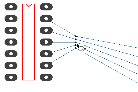
You can use options on the shortcut menu at this stage to alter the gaps between the tracks that will be added.
-
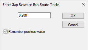
Define Gap Between Tracks - Use this to exactly set the gap between the edges of adjacent tracks to a typed value. Note: the specified gap will only be used if it is not less than the Track to Track spacing.
-
Use Minimum Gap Between Tracks - Use this to make the tracks in the bus route as close as legally possible to each other. It will use the relevant Track to Track spacing between each pair of tracks. This option will not be available if the tracks are already spaced out with the minimum gap.
-
Use Gaps Between Start Items - Use this to set the gaps between the tracks in the bus route so that they are in-line with the start items. This is useful when using bus routing to add memory routing.
-
Increase Bus Route Gaps - This is available if you previously used the Minimum Gap. Each time you use it the tracks will be spread out by another grid step.
-
Decrease Bus Route Gaps - This is available after using Increase Bus Route Gaps to bring the tracks closer together by reducing their offset by a grid step. You can use it until the minimum gap is reached.You can also use Define Bus Route Nets from the shortcut menu at this stage to re-order the nets in the bus route.
Now left click to pick the position to start the bus route from.
-
-
You should now have a new set of parallel tracks dynamically displayed on the screen and are ready to add some track segments to define the bus route path. If you had the Route Connections At Bus Start switch on (see above), the dynamic unrouted connections at the start of the bus routing will be converted to tracks. If the connections cannot be routed simply, they will be left unrouted for you to complete later.
If you are adding an odd number of tracks in the bus route you will be controlling the middle track of the set with the cursor, and it will be added on grid just like if you were adding a single track. If you are adding an even number of tracks it is the centreline of the gap between the tracks that is edited and placed on grid. Note: in the Interaction Options there is a switch to display a dummy thin track line in the middle for you to control on grid. When you have finished adding the dummy track it will be removed. The rest of the tracks will be created either side of the middle track you are adding. This is similar in operation to the Edit Track mode except multiple tracks are added together. See Editing Track Segments for details about adding the track path.
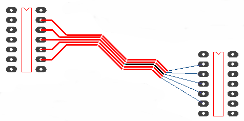
The first track segment added will be forced to use the selected start direction away from the start items. When you have left clicked once to add the first corner, free movement can be used. The segment mode used can be changed from the shortcut menu. Note that small tight corners created in the middle track path might give strange results for the outer tracks being added if they do not have not enough room to maintain their required gap. If you prefer, there is an Interaction Option switch to not allow movement that would create these strange track patterns.
Whilst adding the track segments you can change the gap between the tracks using the various options from the context menu described above. Note that Use Gaps Between Start Items cannot be used at this point. When the gaps are changed, if you had the start connections routed they will be re-routed to accommodate the new track start positions.
-
As bus routes are often added early in the layout process, it is advisable to use the Show Dynamic Cons Only editing option whilst adding a bus route to declutter the nest of connections so that you can only see the connections from the end of the bus route to their target pads.
-
If Show Connection To Net is enabled, as you move the end of the bus route the connections from the end of the bus route tracks will change to end on the nearest node on their net. This option is available from the Editing Options shortcut menu.
-
Once the required path has been added, there are several ways of finishing as follows:
- Use the Finish Here option from the shortcut menu to finish the tracks at the cursor position, leaving the trailing connections as they appear on the screen.
- Use the Complete As Track option from the shortcut menu to finish the bus route at the cursor position and attempt to convert the dynamic unrouted connections at the end of the bus route to tracks, finishing on their end items. A simple routing algorithm will be used that does not allow layer changes or complicated patterns to be created. If the connections cannot be routed simply, they will be left unrouted for you to complete later.
- Move the end of the bus route over a previously created bus route that contains at least as many tracks as you have in the dynamic bus route. This is best done by approaching the existing bus route at the same angle as its last segment. When the end of each dynamic track is over one of the tracks in the existing bus route a weld marker dot will be shown. At this point pressing left click should join each track in the dynamic bus route to its corresponding track in the static one.After finishing the tracks you will be ready to select a different set of pads to add the next bus route from, or use the Esc key to exit the bus route mode.
Related Topics
Insert Bus Route | Cut Track | Differential Pairs | Edit Track | Grids | Online DRC | Segment mode | Status bar | Technology | Track Properties