A direct LPKF Output is available in Pulsonix on the Output menu in the PCB Editor. It provides you with an export via an interface used to output your Pulsonix PCB designs to files used to drive the LPKF prototyping machines.
Shortcuts
Default Keys: None
Default Menu: Output
Command: Output LPKF
Locating this option
Available from: Output menu > LPKF option
Description
The LPKF output is provided to allow you to generate composite .gbx files from the PCB design data suitable for import into the LPKF CircuitCAM Or CircuitPro programs.
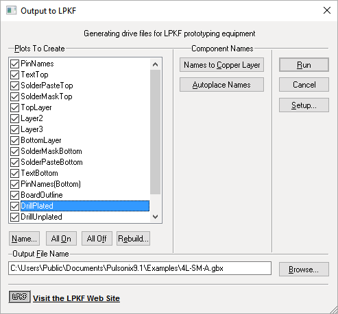
This option is driven from a single dialog:

From the dialog, the layers within the design suitable for output to the LPKF system will be listed using the CircuitCAM format layer names. These translate as follows:
- TextTop and TextBottom - The silkscreen layers
- SolderMaskTop and SolderMaskBottom - The solder mask layers
- SolderPasteTop and SolderPasteBottom - The paste mask layers
- TopLayer and BottomLayer - The outer electrical layers
- Layer* - Inner electrical layers
- BoardOutline - The board outline
- DrillPlated - Through hole layer span
- DrillPlated* - Other layer spans
- Panel* - Only included if you are producing output for a Panel Design. One layer will be included for each of the three types of panel shape, i.e. Outline, Tab-Routs and V-Score lines.
It should be possible to create the .gbx file straight away, by pressing the Run button at this point. For specific selection of layers, use the All On or All Off buttons at the bottom of the layers list in conjunction with the individual selection of layers using the check boxes.
The plots are named using a standard set of names depending on the type and side of each layer. However, if you wish you can change the name of any of the plots by selecting the plot in the list and clicking on “Plot Name”, or simply by double-clicking on the plot in the list.
Setup
The Setup button allows you to change the precision settings of the output . GBX file. This needs only to be changed if using Metric files and a finer precision is to be used. See LPKF Options for details.
The options dialog also allows you to request that all text items are plotted separately, or that all slots are plotted separately. Again, see LPKF Options for details.
Component Names
This option provides the ability to place component names on a copper layer for inclusion in the output file. This feature is currently provided in two discrete steps.
Names to Copper Layer
Pressing this button will examine each component on the board, and will place a duplicate copy of the visible component name on the appropriate copper layer.
The layer chosen will be the top or bottom electrical layer, depending on the side of the board on which the component is positioned. If a component already has an instance of the component name on an electrical layer, no additional copy is created.
Autoplace Names
As well as bringing component names to the electrical layers, it is also possible to automatically place these names so as to remove (where possible) any violations against other items (such as pads and tracks) already on these layers.
On pressing the Autoplace Names button, the position of each component name will be adjusted where necessary to avoid such violations. Where it is not possible to place the name in ‘free space’, a design rule error will be added to highlight this fact.
You should be aware that the component names on electrical layers will now be seen by the autorouter as obstacles and will therefore be avoided. This may cause the router to give a much lower completion rate. It is therefore advised that this process be completed as one of the final processes before design rules checking and generating the Gerber and LPKF files.
This option also has an impact on the autoplace option as the names may well be placed some way outside the component’s original placement bounding box. Again, it is advisable to run this process after using autoplace on the design.
CircuitPro
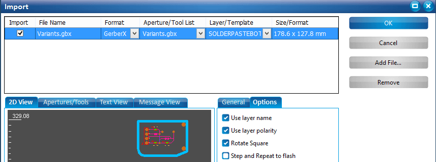
When importing .gbx files created in Pulsonix into CircuitPro, it is important to ensure you:
Enable the Use Layer Name check box available from the Options dialog from the import screen of CircuitPro, as shown below.

CircuitCAM
There are two points to be noted when reading the .gbx files created by Pulsonix into CircuitCAM:
- The file you output from Pulsonix should not be used with the CircuitCAM Import Wizard.
- Under Config, General Settings, Diverse, there is a check box to ignore layer names in Gerber (LN). If using the LPKF output from Pulsonix, this should not be selected.