IPC-2581 is a CAD/CAM data exchange format which can be used as an alternative to Gerber, Excellon or ODB++. Pulsonix currently outputs IPC-2581A format.
Shortcuts
Default Keys: None
Default Menu: Output
Command: IPC-2581
Locating this option
Available from: Output menu > IPC-2581 option
Description
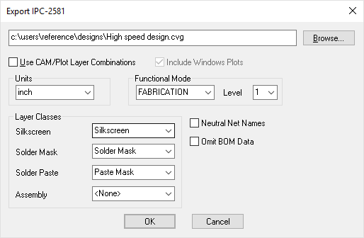
On selection from the Output menu and after initial reported checks, the IPC-2581 dialog is displayed:

File Name - Use Browse to change the destination of the output file.
Checking the Use CAM/Plot Layer Combinations check box means that instead of outputting data for every layer in the design, it will output data for each Gerber and Excellon type plot defined in the CAM Plots page of the Technology dialog.
Windows plots will be included if Include Windows Plots is checked. (Windows Plots will be directed to your current default installed Windows device).
Units
Choose the Units required for the IPC-2581 export. From the drop down list, choose Inch, Micron or mm.
Functional Mode
The IPC-2581 export is capable of outputting all or partial design files based on your requirements. From the drop down list, choose between FULL, DESIGN, FABRICATION, ASSEMBLY or TEST. Each of these modes will give you different portions of the design to suit the process it is intended for.
The Level drop down list is available for all outputs except FULL. This enables you to choose the detail level for each functional mode selected. Choose between levels 1, 2 or 3.
Full contains all IPC-2581 data that we output
Design Level 1 represents the design as was used to layout a PCB from the design schematic, layout design rules and component information.
Design Level 2 provides information to modify an existing design using the original CAD data.
Design Level 3 information is used to modify an existing or archived design where the original hierarchical information was not maintained or may not be compatible with the design system.
Fabrication Level 1 represents single, double sided, or multi-layer PCB graphical data.
Fabrication Level 2 as with level 1 but also with electrical connectivity data.
Fabrication Level 3 as with level 2 but also with embedded passive information.
The Omit BOM Data switch is available with any Fabrication Level set. Use this to remove the BOM data from the IPC-2581 file to hide company specific Parts names, this will help protect your design IP.
Assembly Level 1 represents pure assembly information.
Assembly Level 2 information represents assemblies that are to built to print.
Assembly Level 3 information represents a full service assembly process.
Test Level 1 provides testing for bare board only.
Test Level 2 provides testing capability for inspection, manual or using automated equipment.
Test Level 3 provides testing capability for full electrical testing.
Layer Classes
In the IPC-2581 format the Silkscreen, Solder Mask, Solder Paste and Assembly layers need to be identified. Use the appropriate drop down list to select the Layer Class which will identify these layers. You can select (None) if you are not interested in the layer type.
If there are no power planes in the design these options are suppressed.
Neutral Net Names
If this is checked then all user defined net names will output as numerical net names. This can be used to hide company specific net names, this will help protect your design IP.
Omit BOM Data
The Omit BOM Data switch is available with any Fabrication Level set. Use this to remove the BOM data from the IPC-2581 file to hide company specific Parts names, this will help protect your design IP.
Panel Editor Specific IPC-2581 Switches
When running the Panel Editor, there is a switch that is only visible when running the IPC-2581 option:

Output Each PCB Design Contents
By selecting this check box, a copy of each of all the PCBs in the panel are exported. With it not selected, none of the contents are exported.
IPC-2581 Viewers
There are IPC-2581 viewers available so that you can check the output before sending to external sources, this is highly recommended.