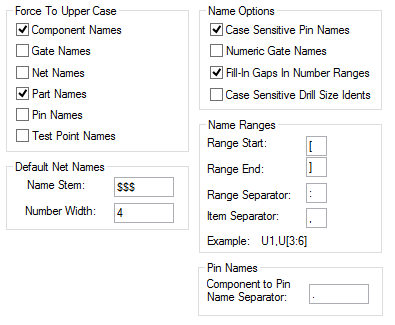
This tab allows you to setup various fundamental aspects of the design and how it will use the design data you provide. In particular it defines the naming conventions you will be using, which are important in allowing you to interface between the schematic and PCB, and with other tools you may be using. It is recommended that you set these parameters in the technology files you will be using before you start designing.
Shortcuts
Default Keys: None
Default Menu: Setup
Command: Design Settings
Locating this option
Available from:
Setup menu > Design Settings option > Naming page
Setup menu > Technology option > Design Settings > Naming page
Using the Naming Tab

Force To Upper Case
The names of all entities (except pins, see below) are considered case insensitive by the program. That is, a mixture of upper and lower case letters can be used, and upper and lower case letters are considered the same. So if you have a net called ‘Vcc’ you cannot have a net called ‘VCC’, because the names are considered the same. It is sometimes desirable to have all the letters in names to be of the same case, so that no confusion can result. This is particularly true if you are interfacing with a system which is case sensitive, that is, it would treat ‘Vcc’ and ‘VCC’ as different names. Each of the different name types can be forced to upper case, by checking the appropriate check box in this dialog. This only applies to new names which you are entering, so you should ensure the correct settings are made before you begin designing.
Default Net Names
When you add a new net to the design, it is assigned a default name, this can subsequently be named if you so wish, but this part of the dialog is concerned with the format of the default names. The default name consists of an optional stem followed by a number (which are allocated sequentially). The name stem is specified in the top Name Stem control. The Number Width control specifies the minimum width of the number, which will be padded to the left with leading zeroes.
For example, a stem of ‘Net’ and a width of ‘2’ gives net names of the form ‘Net01’. You can change these values after you have begun designing, but this will result in nets being renamed, which could be undesirable.
Name Options
Checking the Case Sensitive Pin Names box forces pin names to be case sensitive. That is, ‘A1’ and ‘a1’ would be considered different. This is particularly useful if you will be using large pin arrays, where a leading letter designates the row, and you require more than 26 rows.
The Numeric Gate Names box is included here to allow you to match it to the corresponding switch in the Schematics design. It is used when reporting gate swaps.
Checking the Fill In Gaps In Number Ranges box forces names for new Components, Test Points, Branch Points, and Star Points to fill in any gaps between name numbers before adding to the end of the number range. For example, if there are names ‘A1’ and ‘A3’, having this option checked will add ‘A2’ before adding ‘A4’.
Checking the Case Sensitive Drill Size Idents box forces drill table idents to be case sensitive. That is, ‘A’ and ‘a’ would be considered different when checking for unique drill idents in the drill size table. When this switch checked, any idents generated for new pad styles will use a lower case letter if the style is plated.
Name Ranges
This functionality is mainly provided to maintain compatibility with the schematic functionality. In PCB, it will prevent you from entering Component Names which would cause a problem when back annotating, because they would represent multiple components in the schematic.
Pin Names
This specifies the separator to be shown between the Component and Pin names when ever the pin name is shown. For example ‘X1.1’
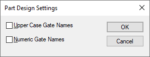
Design Settings for a Part
When editing a Part or Part technology, the Part Design Settings dialog is displayed from within the Setup menu:

Upper Case Gate Names
Numeric Gate Names
Use these check boxes to define how the gate names will look like on the gates page. Set these switches in your Part Technology to match your schematics gate name notations.
Related Topics
Drill Size Table | Parts Editor | PCB Technology Files | Net Names | Character Set | Insert Text | Insert Attribute | Insert Attribute Position | System Attributes | General | Name Ranges in Schematics