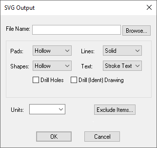
This dialog is used to set up the SVG output parameters that do not generally change from design to design. The values set up here are maintained between program sessions so you should only need to set them up once, to correspond to the plotter you are going to use.
Locating this option
Available from: Output menu > CAM Plots > Plot Settings > Setup - SVG button
Using the dialog
The Setup SVG dialog is accessed from the Plot Settings page of the Output CAM dialog.

File Name
This File Name field defines the name that the SVG file will be given when it’s output.
The Browse… button next to this allows you specify the location on your computer where the file will be output to.
Draw Settings
The options in this section detail how Pads, Lines, Shapes, and Text should be drawn within the SVG output. In all but the Text option, these can take the form of Solid, meaning that the item in question will be filled with the same colour as it’s outline, or Hollow, meaning that only the outside stroke is visible.
The Drill Holes checkbox allows to you to have drill holes drawn in the SVG or not. Similarly, the Drill (Indent) Drawing option determines whether drill drawing letters or symbols should be included in the SVG, as would normally be shown on a drill drawing plot.
Units
You can change the Units that you want to be used in the SVG file, for use wherever sizes or coordinates are to be detailed, whether that be Metric or Imperial.
By default the units used are your design units.
Exclude Items
To Exclude individual design items from the output file, click the Exclude Items… button to enter the Exclude Items dialog to specify what you want excluded.