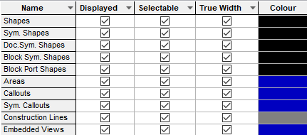
The colours dialog defines the colours used on each category of item within the design.
Shortcuts
Default Keys: C
Default Menu: Setup
Command: Colours
Locating this option
Available from: Setup menu > Colours
The Colours Dialog
The colours dialog has a number of tabs which are used to define the colour, visibility and selectability of the design item types. Each tab contains a table which normally has three cells for each type of item.

- Displayed defines if that type of item should be displayed.
- Selectable defines if that type of item can be picked (in PCB the item is also drawn in a dimmed colour). This is very useful when you are performing edits in a dense area of the design, or if you do not want to be able to edit certain types of item.
- Colour defines the colour the item will be drawn in (specific items may be drawn in other colours due to highlighting, etc). Clicking on the colour cell brings up the colour palette, where you can select a predefined colour, or define a custom colour by selecting Other…
You can change all the cells in a given row or column to the same value, by selecting one of the cells, pressing the right-hand mouse button, and selecting Apply to entire Row/Column from the context menu which will appear.
It is recommended that you set up your colour preferences in your technology files, so that new designs are created with the correct colour settings.
Colour Dialog Tabs
Schematics designs, technology, profiles and symbols have the following colour tabs:
- Attributes defines the visibility and colour of all attributes
- Bus & Connections defines the visibility and colour of Busses, Connections & Connect Guides
- Component Rules defines a colour rule to apply to matching component Doc Shapes and Text
- Connect Points defines the visibility and colour of pins and junctions
- Differential Pairs configure each Differential Pair to be drawn in its own colour
- Highlights defines the visibility and colour of various types of highlights which override the normal colour of an item
- Nets configure each net to be drawn in its own colour
- Others a catch all for non-layer based items, the background, origins, etc.
- Shapes defines the visibility and colour of all shapes, including areas and text callouts
- Signal Paths configure each Signal Path to be drawn in its own colour
- Sub Nets configure each sub net to be drawn in its own colour
- Text defines the visibility and colour of all text entities (but not attributes)
In schematics, the same colours apply across all pages of the same design.
Items with local colours
Individual documentation shapes and text items can have their own colour, overriding those defined in the colours dialog.
Grids also have their own colours and these are defined in the grids dialog.
Save & Load Colours
You can save your colour settings to a file in the Colours folder for later use. This is a convenient way to store and retrieve commonly used colour and visibility settings.
Please visit Loading a Cut Down Colours File on how to create and load a cut down colours file.
Related Topics
Technology Files | Shape Properties | Text Properties | Grids | Save Colours | Load Colours