Variants allow the creation of multiple build assemblies within a Schematic or PCB design file. A design with variants has a common bare board (which means that all pads, tracks and copper do not vary), but with component differences, such as a different values, a different footprint or a different Part in each variant.
The Variants Manager dialog allows you to enable, create, modify and manage the variants for your design.
Once the variant names have been set up, use the Component Variant Spreadsheet from the Edit menu to change the variant states of components in the design.
Variants are stored as a facet of your design but are also part of the Technology file
Shortcuts
Default Keys: None
Default Menu: Setup
Command: Variants
Locating this option
Available from: Setup menu > Variants option
Available from: Setup menu > Technology option > Variants Manager page
How to use the Variants Manager dialog
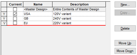
Initially in a design, variants will not be in use. Press New to create the first variant. This
will automatically create the

Once variants have been created for a design, at any given time, one particular variant from the Variants List will be considered to be the Current Variant. This is indicated by the checked box in the Current column. This is the variant that is currently active in the design and will affect not only the view of the design on screen, but also the results of variant specific functionality such as Parts List output and Plotting.
Each variant has a unique Name and an optional Description. By selecting the appropriate row in the grid. The information on that variant is shown in the editing panel below the grid.
The Variants list always includes a default
The Used column indicates if there are any items in the design utilising this variant, in particular, components which are not fitted in that variant, or Design Attributes which have a different value.
Navigation
The buttons to the right side of the dialog are used to navigate the grid, the general common buttons are detailed on the Technology Navigation page.
When using New, there is no limit to the number of design variants that you may add.
Copy
The Copy button will create a new variant which is identical, in terms of the components it contains, to the Current Variant. It will then display the Edit Variant dialog so its name and description may be changed to something different from the current one.
Delete
The Delete button will remove the Current Variant from the design.
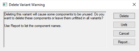
If the variant is still used in the design, e.g. there are components that are Not-fitted in the variant, you will be warned and asked to confirm the deletion.

Delete, will delete the components from the design.
Unfit will unfit these components from all variants, but will remain in the design.
Cancel will cancel the delete and return you to the Variant Manager dialog.
Report will generate a list of components that are in the soon to be deleted variant and not in any other variant.
Move Up and Move Down
When using Move Up and Move Down, the
Using the editing pane

Name:
The Name field will contain a unique name for your variant. Type the name you require into the text box.
Description:
An optional Description can be added. This is displayed in most places when the variant name is shown, such as Properties of a Component. This text can be extracted through the Report Maker if required.
A Variants Report is available from the Reports dialog. This basic report lists all the variants defined for a design and shows the components fitted in each one.
Global Settings
Not-Fitted Components
Display
Checking the Display check box for Not-Fitted Components in the Variant Manager dialog will force components to be fully displayed in the design view on screen even when Not-fitted. The Not-fitted components will be highlighted on screen in the Not-Fitted Colour and/or by their outline shapes being drawn in a special Variant line style defined on the Design Settings Defaults Variants page.
The Variants Colour is used to highlight all components that are flagged with one of the variants status in the design. This helps you identify component variants quickly. In addition, the Not-Fitted Colour also further helps identify components within a variant that are fitted or Not-fitted.
Note: this option only affects the screen display and not the CAM Plot output which is controlled by the separate Plot option described below:
Plot
For Schematic designs only, the Plot check box enables you to select whether Not-Fitted components are plotted or not when using the CAM Plots option. Not-fitted components will be highlighted in the plot using the outline shape drawn in the Design Settings Defaults Variants Line Style and where applicable in the Not-Fitted Colour.
Show Attributes

The Show Attributes check box is normally checked so that component attributes are shown for unfitted components.
Uncheck this option to not show attributes on an unfitted component. The Show and Replace Attribute controls are then available. The only attributes which will be shown are the Component Name and Pin Names.
You can also optionally show a selected attribute and replace the value with the fixed text specified. For example, you can make a Value attribute show Not Fitted for every unfitted component.
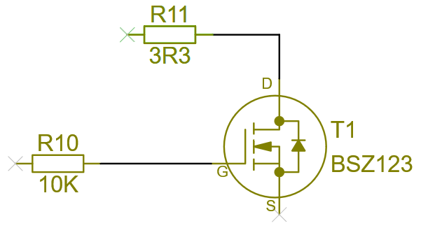
The example below shows components in a Variant that are not fitted. The Value attribute is displayed with the Shows Attributes switch on.

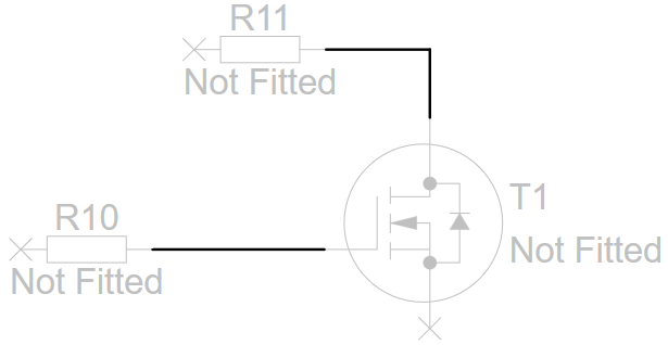
With the Shows Attributes switch off and the Value Attribute substituted with the words Not Fitted, it now displays like this:

Show Variant on Status Bar
Check this option to show the current variant name on the status bar.
Part Variants
It is sometimes desirable to have a component with the same name but different values, a different footprint or a different Part in each variant. Creating this level of component variant is more fully explained on the Component Variants Properties page.
Documentation Shapes, Text and Text Callouts in Variants
Documentation Shapes, Text and Text Callout items in a design may be set to only appear in specific variants using the Variants tab of the shape, text or text Callout Properties dialog.
Design Level Attribute in Variants
Attributes added at the design level can be made specific to a particular variant or variants using the Variant Attributes tab of Design Properties.
Related Topics
Technology Overview | Component Variant Spreadsheet | Component Variants Properties | Variant Attribute Properties | Variant Shape or Text Properties | Variants - Advanced View