The Spacing Rules dialog pages are used to specify the minimum clearances required between different kinds of electrical design items. The spacings you set up in this dialog are used by Design Rule Check to calculate whether or not any of the electrical items in your design are too close together.
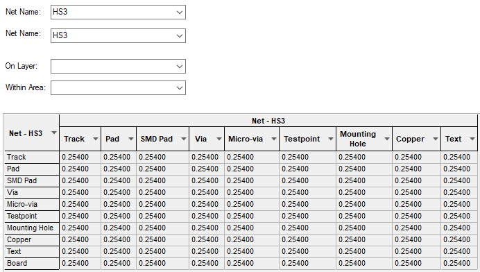
For more advanced requirements, it is possible to define different spacing rules for nets using a particular Net Class, or even between specific nets on a specific layer, or even within a named area.
Note: as well as the spacings defined here, any net can have an additional Guard Spacing applied. This is set up on the Nets Page of the PCB Design or Footprint Technology dialog or via the Net Properties dialog.
A detailed description of how spacings are determined is given here.
Shortcuts
Menu: Setup
Default Keys: T
Command: Technology
Locating these options
Available from: Setup menu > Technology > Spacing Rules pages
Using the dialog
To display this dialog, select Technology from the Setup menu, then select one of the Spacing Rules tabs.
In each page the spacing values are presented in a grid, allowing you to easily change and view the values directly. Click on the text of the value you wish to change, and edit the text to show the required value. You can also take the value from one cell and apply it across the whole row, down the whole column, or to all the cells of the whole grid, by pressing the right-hand mouse button and selecting the required option from the context-sensitive menu. Greyed out cells cannot be changed, either because they are not relevant, or because the reverse spacing is equivalent (i.e. Track to Pad is the same as Pad to Track).
All pages are available for a PCB Design; [Design Level](#Design Level), [Net Class Level](#Net Class Level), [Match Pair Level](#Match Level) and Check Spacing Values
For a Footprint you can only define [Design Level](#Design Level) spacings and only between items relevant to a Footprint design.
The Schematic pages only allow [Net Class Level](#Net Class Level) and [Match Pair Level](#Match Level) rules to be defined for critical nets. You can also view the Check Spacing Values page.
Design Level Rules
Design Level Rules define the default minimum distance between items.

As well as Design Level Rules, you can also specify additional design level rules for Board, Bond and Die Pad, Component, Copper, Drill and Pad.
Net Class Level Rules
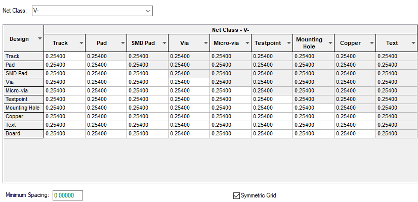
The Net Class Level Rules define the minimum spacing between items on a net using the named Net Class (columns in the grid) and all other design items (rows in the grid). Select the required Net Class from the list.

Colour Coding For Grids
The grid is colour coded to show what values apply:
Black for inherited [Design Level](#Design Level)
Green for Minimum Spacing
Blue for an explicit value
You can change a value back to the default by selecting the value in the grid and deleting it.
Match Pair Level Rules
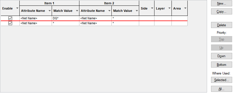
The Match Pair Rules are similar to the Net Class Level Rules, except they only apply between two Nets.

Import CSV
Use this button on the Match Pair Rules page to import Net Class level and Class to Class Level spacing rules into the schematic or PCB design using a CSV file. See the Import Class To Class Spacings help page for more details on importing spacings.
Check Spacing Values
The Check Spacing Values page presents a read only grid which will show you the actual spacing used between items on the two specified Net Classes. This resolves all the rules specified in the three rule levels. You can optionally provide a layer side or layer name, to get these specific spacings. This page is for information only, and the values cannot be edited there.

How the rules are applied
Given two nets (and a layer and an optional area name), and two items on those nets (maybe a Track and a Pad), apply the following rules, until the spacing value is determined.
-
- Find the first matching Match Pair, if there is one.
- If so, if there is an explicit value for the pair of items, then take that value.
- Otherwise consider the Minimum Spacing value for the pair.
-
- If no explicit value has been found - find the rules defined for each of the two Net Classes.
- If there is a specific value assigned to the pair of items on one of the Net Classes, use that value.
- If specific values are defined on both Net Classes, take the larger.
- Otherwise consider the largest of:
- the Minimum Spacing values defined for the net classes.
- any Minimum Spacing value inherited from a matching Match Pair.
-
- If no explicit value has been found - find the value defined at the Design Level.
- Take the maximum of the Design Level value and any inherited Minimum Spacing values.
-
- Determine the maximum of any Guard Spacing defined on the two nets and add this.
Related Topics
Technology Overview | Design Level | Net Class Level | Match Pair Level | Check Spacing Values | Importing Class To Class Spacings | Nets Page | Design Rule Check | Using Spacings By Area