Use this to reload Parts, Symbols, Footprints and Documentation Symbols within PCB and Schematic designs, with updated items from their corresponding libraries or the Vault.
For this purpose you have three options available from the Utilities menu:
- Reload All
- Reload Browse
- Reload Selected
Shortcuts
Default Keys: None
Default Menu: Utilities
Command: Reload All Lib Items
Default Keys: None
Default Menu: Utilities
Command: Reload Browsed Lib Items
Default Keys: None
Default Menu: Utilities
Command: Reload Selected Lib Items
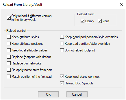
Reload All
This is used to reload all the Parts, Symbols, Footprints and Documentation Symbols within the design.
Reload Browse
Use this dialog to browse the Parts, Associated Parts, Symbols, Footprints and Documentation Symbols used within in the design to choose for reload. The example dialog shown is from a Schematics design:
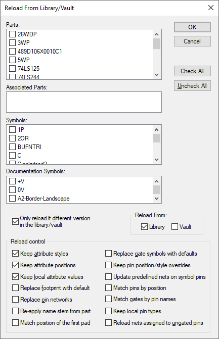
Use Check All to select all items, or Uncheck All to clear the selection.
The options are defined in the ‘Performing The Reload’ section below.
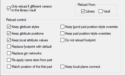
There are different options when using this feature from a PCB Design:
Reload Selected
This will only reload the parts for the selected components within the design.
Reload Selected can be run in a Latched Mode. This means the operation is invoked when there is nothing selected in the design. The Reload tool will be “latched down” allowing you to reload parts as you pick them. This will continue until Escape key is pressed or another operation is started.
Performing The Reload
When the reload process is started, if you did not use the Browse method of starting it you will be presented with a confirmation dialog:
Check the Only reload if different version in the library box if this is required. Leave it unchecked if ALL chosen items are to be updated even if their version is the same as in the library.
Reload Control
Options common to PCB & Schematics
- Check the Keep attribute styles box if you do not want the attribute styles reset to their values in the symbol in the library.
- Check the Keep attribute positions box if you do not want the attribute positions reset to their values in the symbol in the library.
- Check the Keep local attribute values box if you want all attributes currently on your Component to be retained.
- Check the Replace footprint with default box if you want the footprint to be replaced with the first footprint on the reloaded part. Leave unchecked to keep the footprint used in the design (if it is a valid footprint for the new part). If editing a schematics design the footprint is an attribute that indicates which footprint to use in the corresponding PCB design.
- Check the Replace pin networks box to replace any existing pin networks with any defined on the library part. Replacing pin networks will result in the existing components associated with a pin network to be removed, and new components to be placed in the bin.
- Re-apply name stem from part, if the name stem defined in the part is different to that currently used by the component, then the component will be renamed. The name stem is the alphabetic part of the component name (e.g. the U in U1).
- Match position of the first pad, when checked, the position of the reloaded component is determined by matching the position of the first pin on the symbol, rather than the symbol origin.
- Reload Doc Symbols, when checked, Documentation Symbols are reloaded as well as Parts and associated Symbols or Footprints. This option is only available if you a reloading All symbols.
PCB only options
- When checked, Keep bond pad position/style overrides, will retain the positions and styles of the bond pads which have been placed in the design. Unchecking will cause all bond pads to return to the position and style defined in the footprint.
- When checked, Keep pad position/style overrides, will retain any moved pads and pad style reassignments. When unchecked, all pads will receive the position and style defined by the footprint.
- Do not reload footprint, when checked, will prevent any footprints from being reloaded, only the part information will change. This option should be used with care because the component may not be consistent with the library.
- Keep local plane connect, will retain the plane connect value if it has been changed from the value defined in the footprint. When unchecked, all pads will receive the plane connect value defined in the footprint.
Schematic only options
- Check the Replace gate symbols with defaults box to reset the gates to the default symbols specified in the part. Leave unchecked to retain the symbol alternate currently selected.
- Check the Reload nets assigned to ungated pins box to reset the pins on the component that are not on gates, to be on the nets on the pin definitions in the part in the library. Leave unchecked to keep the component’s ungated pins on the nets already assigned to them in the design.
- Check the Update predefined nets on symbol pins box to connect symbol pins to the net names defined in the part. Only pins which are not currently connected or are currently connected to the net name previously defined in the part, and do not have a connection to them, are updated.
- When checked, Keep pin position/style overrides, will retain any moved pins and pin style reassignments. When unchecked, all gate pins will receive the position and style defined by the symbol.
- Match pins by position, will cause the connections to be connected to whichever pins are at the right location. This option is therefore likely to change the connectivity of the design.
- Match gates by pin names, this will not normally be selected but is available if you have imported a design using one of the import filters but the gates have been created in a different order from the library.
- Check the Keep local pin types box if you want any pin types that have been overridden locally in the schematic design to be retained. Uncheck the box to always replace a pins type from the library part.
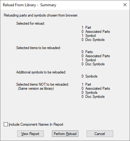
The system will then analyse the design and work out which items will be updated. When this is complete you will be presented with a summary dialog in order to decide whether to go ahead with the update, or just produce a report at this stage.

A report is available at this stage showing which parts and symbols will be updated. Use Include Component Names In Report to include actual lists of names of components that will be updated.
By using the Reload All option, and ‘Only reload if different version in the library’ switch, you can use the View Report button to get a report of which library items used in the design have been updated in the libraries since you created the design.
Press Perform Reload to carry on with the reloading. If you had errors, detailed in the summary dialog, but did not notice you will be presented with the following warning:
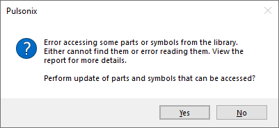
Press Yes to perform the reload on the parts and symbols that can be found in the libraries. Press No to abort at this stage.
Using with the Vault
If the Vault is in use, some dialog controls will appear slightly differently.

You have the option to reload parts and symbols from your Pulsonix libraries, the Vault, or both.
Reload from both Library and Vault
If both options are checked, items in a design will be reloaded from both your Libraries and the Vault with precedence being determined by the Library Folders search order. Parts in the design that originally came from the vault will only be replaced with parts with the same Vault Item ID. The versions of symbols used by parts from the vault is dictated by the part and is not necessarily the most recent version available.
If using the vault, it is important to note that doing a partial reload of a design may leave it unable to be Checked In to the vault. If only some of the parts and symbols contained within a design are reloaded it may lead to vault version inconsistencies of referenced items. If Reload All is used, the versions of referenced symbols used by parts will be checked for consistency. Even then, because only a single version of a named library item is allowed in a design, the case may arise where different parts in a design try to reference different versions of the same symbol. If this situation arises, the library items in the design will need to be standardised before it can be checked in to the vault. To achieve this a new version of a part that references the same vault version of a symbol as the other parts in the design should be created in the vault and reloaded into the design.
Reload from Vault only
If only Vault is checked, items in the design will only be replaced with items from the vault. Parts that previously came from the vault will only be replaced with parts with the same Vault Item ID. Parts that did not previously come from the vault will be replaced with parts from the vault with the same name. The versions of symbols and footprints used by parts from the vault is dictated by the part. Those used by parts not from the vault will be replaced with ones from the vault with the same name.
Reload from Library only
If only Library is checked, items in the design will only be replaced with items from your libraries and not the vault. Parts, whether previously from the vault or not, will be replaced by parts from the libraries with the same name. Symbols and footprints used by parts no longer from the vault will be replaced with ones from the libraries with the same name. Note that using this option can strip vault information from library items in a design and render the design unable to be Checked In to the vault.
Connected Components
If your component was connected, it would normally be reloaded with a component with the same number of pins in order to not affect the nets. The connections or tracks will be attached to the pads with the matching pin name in the new part.
If you reload a part with more pads, the extra pads will remain unconnected in the design. If you reload a part with less pads than on the component, any connection to a pad that does not exist on the new part will be removed, and any track in the same situation will be disconnected and left dangling for you to sort out in the design later.
For schematic components, as well as pins being matched up, gates are matched so that if you reload a four gate component with a single gate part, only pins on the first gate of the original component will retain their connectivity. All connections to pins on unmatched gates will be disconnected and left for you to sort out later.