This tab allows you to setup various fundamental aspects of the design and how it will use the design data you provide. It is recommended that you set these parameters in the technology files you will be using before you start designing.
Shortcuts
Default Keys: Shift+D
Default Menu: Setup
Command: Design Settings
Locating this option
Available from:
Setup menu > Design Settings option > General page
Setup menu > Technology option > Design Settings > General page
Using the General Settings Tab

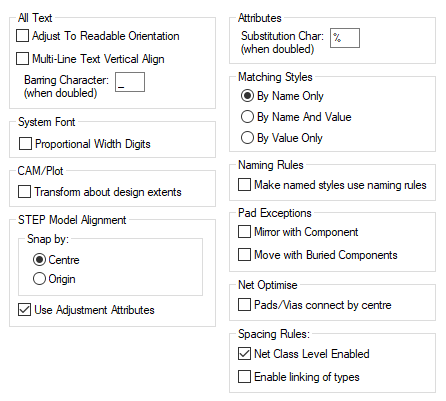
All Text Options
These options apply to all text based items, that is free text, attributes and names, when they are displayed in the design.
Adjust to Readable Orientation will force all text items to an orientation such that they are readable from the bottom or right side of the design (bottom or left side for mirrored items). This is regardless of the actual rotation that has been assigned to them. This makes it much easier to produce readable drawings. This option can be overridden for a single piece of text by using the Ignore Readable Orientation option in Text Properties or Attribute Properties.
Multi-Line Text Vertical Align when checked, causes all multi-line text to vertical align using the height of all the lines of text. When unchecked, vertical alignment is based on the first line only.
Barring Character (when doubled) allows you to define a character which can be used within any text to produce a barring line (a horizontal line) above a part of the text. The character defined is doubled to produce this effect, so it is less likely to be introduced by accident. Repeating the barring characters turns off the effect.
So, if you define the barring character to be ’_’, then ‘This is __barred__ text’ will make the word ‘barred’ have a line drawn above it. It is not necessary to turn off the effect if you want it to run to the end of the text.
System Font
The System (Stroke) Font offers a choice of Proportional Width Digits or (by not selecting the check box), Fixed Width Digits. If you have no strong preference, it is recommended that you leave this option unchecked and use Fixed Width Digits. Tables of numbers will then align correctly.
CAM/Plot
By default, the transformation of plots is about the centre of the plot extents (working area, designated area, or board outline). For backwards compatibility you can set the transformation origin to be the design extents (by selecting the Transform about design extents check box)
- unless you know otherwise, it is best to leave this option unchecked.
STEP Model Alignment
See STEP below under PCB Only Settings.
Attributes
The attribute Substitution Char: (when doubled) defines a character which when used in an attribute value, delimits the name of another attribute name, the value of which is to be substituted. This is also called dynamic attributes or plugged attributes; where the attribute name is derived from other attributes dynamically. The character is doubled to produce this effect, so it is less likely to be introduced by accident.
For example, with the Substitution Character set to it’s default %, a component with the attribute ‘Resistance=400’ and an attribute ‘ResistValue= ohms’, the resulting value of ResistValuewould be ‘400 ohms ’, and changing the value of Resistance will also change the value of ResistValue.
Taking another example, in a design that is defined to have two variants; US and EU, the following design level attributes could be defined:
US_Stock_No=“USA-1234”
EU_Stock_No=“EUR-1234”
Variant_Stock_No=”%
Then, if the Variant_Stock_No attribute was displayed in the design, it would show the appropriate stock number value for which ever variant was currently active in the design, i.e. if the US variant is active then the % part of it’s value will initially resolve to US to yield the attribute value * which will reference the attribute of that name whose value USA-1234 will be substituted and ultimately displayed.
The attribute substitution capability also allows dynamic attribute name
substitution based on the value of another attribute. A ‘nested’ attribute name
substitution can be indicated by adding an extra substitution character, e.g. **. This can be useful for achieving attribute
switching based on the value of another attribute such as the
built-in
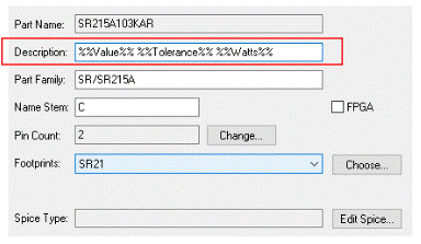
It can also be used for example to autogenerate a Part Description from other attributes on the Part, as you can see in the picture below where attribute substitution is used to define which other attributes are used to build up the description.

Matching Styles
This option defines which style will be used when (for example) adding a symbol into a design. A search of the currently defined styles in the design will be made to see if there is a style of that name. If a style in the design has the same name and the values also match the style from the library, then this style will always be used.
If no exact match is found, one of the following actions will be used:
- If By Name Only option is used, the style in the design with the same name will be used no matter what it’s values are. If there are no styles of that name then a new style of that name will be added to the design.
- If By Name And Value option is used, the name is incremented (by incrementing or adding a number at the end of the name), if a style exists which matches the incremented name and also the values, then this style is used, otherwise the name is incremented until no style with that name exists. A new style is then added using the incremented name. An exception to this is when a library reload is being performed and the existing style would become unused if the above name incrementing were performed. In this case, the existing style is reused, the values being changed to match the required style.
- If By Value Only option is used and a style in the design has the same values matching the style from the library, then this style will be used. Otherwise a new style will be added, the name being incremented if necessary, to make it unique.
These rules apply to Pad/Pin, Track/Connection, Line, Text and Hatch styles. These rules are also used when copying and pasting from one design to another.
Naming Rules
Use the Make name styles use naming rules check this box if you wish to make name styles use naming rules. Leave it unchecked will enable you to type the style names as required.
Pad Exceptions
See Pad Exceptions below under PCB Only Settings.
Net Optimise
See Net Optimise below under PCB Only Settings.
Spacing Rules
Net Class Level Enabled allows Net Class Level spacing rules to be defined. Unchecking this option will remove any Net Class spacings and not show the Net Class Level page on the Technology dialog.
If Enable linking of types is checked, then by default, some pairs of item types are linked together on the spacing rules grids (Pad - SMD Pad, Via - Micro-via, Track - Copper). When this is done, some rows and columns on the spacing grid will disappear (provided the spacings are the same), and the values are linked together. You can show the hidden values by unchecking the appropriate options which appear under the spacing grid.
PCB Only Settings

STEP Model Alignment
Centre will align the Footprint and the model using bounding box centres (in the same way as in Pulsonix 9.1 without the No Model Transformations check box selected). If the model is orientated differently to the footprint it will be automatically rotated accordingly.
Origins will align the origin of the Footprint with the (0,0) in the model without reference to bounding boxes or areas (in the same way as in Pulsonix 9.1 with the No Model Transformations check box selected).
The Use Adjustment Attributes option will effectively do the same as above in 9.1 and ignore the < STEP Offsets> and < STEP Rotations> attributes, regardless of the Snap by: value.
More details about STEP Model Alignment can be found in Using STEP Models and Attributes
Pad Exceptions
Use the Mirror With Component box to achieve mirrored pad stacks. If this box is checked, any Pad Style by Layer exceptions used on pads in mirrored components will have their layer swapped to the other side.
Use the Move With Buried Component box to allow Pad Style by Layer exceptions assigned to the correct facing outer layer set to appear on the facing layer set of a buried component. Effectively, this allows the pad Exceptions to follow the buried component as it moves down the layer stack. For example, a Solder Paste exception on the Top Solder Paste layer would appear on the Solder Paste layer associated with the top facing layer a buried component is placed on.
Net Optimise
Pads/Vias connect by centre - if checked, this option will cause Optimise to force a connection (and therefore not properly connected) unless the centre of a pad or via is within the shape of the other item. This prevents pads which just touch the edge of a shape from being considered connected. Otherwise, a connection is made if the shapes touch.
Schematic Only Settings
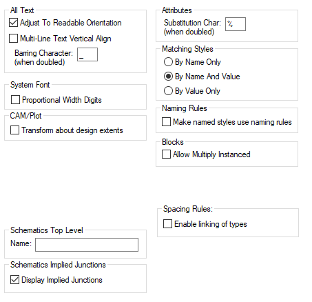
The Schematic Design Editor has some slightly different settings available, these are detailed below.

Blocks
Allow Multiply Instanced - enable this option to allow multiply instanced blocks. That is, blocks which share the same definition and edits on one instance can be applied to the other instances. Without this, each instances is completely independent. If blocks were added without the option being set, then they would be independent blocks. If the option was then set, those blocks would not become instanced, they stay independent, but any new ones added using Insert Block would be instanced. Generally, it is best to set this option before any blocks are added.
Under Schematics Top Level the Name: is used in hierarchical schematic designs. It is the name of the top level owner scope and is applied to net names local to the top level (i.e. not in a block instance), using the naming rules.
Draw Implied Junctions on Schematic Pins - When checked this will display a junction where two or more connections are attached to a symbol pin. The junction will take the style set in the Junction Defaults tab. It will also obey the Colour Settings for Connect Points - Junctions.
Related Topics
Naming (SCM) | Synchronisation | Parts Editor | PCB Technology Files | Character Set | Insert Text | Insert Attribute | Insert Attribute Position | System Attributes | Name Ranges in Schematics | Styles By Area | Output STEP | Track Impedance Calculator | Variants