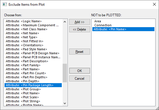
This dialog allows you to modify a CAM Plot to selectively exclude categories of design items from a plot.
Shortcuts
Menu: Setup
Default Keys: T
Command: Technology
Locating this option
Available from: Setup menu > Technology option > CAM Plots tab > New or Edit > Exclude button
Available from: Output menu > CAM/Plot option > CAM Plot tab > New or Edit > Exclude button
Using the dialog
From the Plot Wizard Process Tab press the Exclude Items button. This brings up the Exclude Items dialog.

The dialog contains two lists. On the left is a list of design items, named groups and attributes which could be excluded from the current layer or page. On the right is a list of items and attributes which are currently excluded and will not be plotted. You can move items between the two lists using the Add >> and <<Delete buttons.
These settings are used by the Plot option when generating the actual plots.
Specific PCB Settings
In a PCB design the System Attribute
In PCB you should also consider the Layer Class which can also be used to exclude items such as types of pads and the board outline.
Note: you can exclude Drill, which will prevent drill holes from being output regardless of the Layer Class setting.
Related Topics
CAM Plots | Plot Wizard | Plot | Technology - Layer Class | System Attributes | Groups