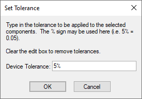
Use this to set the allowable device tolerance for components.
These device tolerances are used when running a Monte Carlo Simulation.
Shortcuts
Default Keys: None
Default Menu: Simulation
Command: Edit Tolerance
How To Set A Component’s Tolerance
Select the component(s) that you wish to change. If all resistors or capacitors are to be set the same tolerance, use the Select All Resistors or Select All Capacitors options from the Monte Carlo sub-menu on the Simulation menu.
Now use the Set Tolerance option from the Monte Carlo sub-menu on the Simulation menu.
The following dialog will be displayed:

Enter the tolerance in the edit box. You may use the ’%’ symbol here if you wish, so 5% and 0.05 have the same effect.
If the value is set to
Which Component Types?
The type of the component is defined in its Part using the Edit Spice Dialog.
Device tolerances can be applied to the following component types:
Capacitors
Resistors
Inductors
Fixed voltage sources
Fixed current sources
Voltage controlled voltage sources
Voltage controlled current sources
Current controlled voltage sources
Current controlled current sources
Lossless transmission lines (applied to Z0 parameter)
Related Topics
Define Component Value | Define Spice Type | Matching Components | Monte Carlo Simulation | Monte Carlo Tolerances | Set Match Tolerance