Insert Signal Reference is used to insert a documentation symbol to show a reference to a signal in a schematic design. This might be Doc Symbols such as Signal References (Power and Ground Symbols), Pointers, or it could be Bus References, Net Labels or Page Links. Other Doc Symbols are handled in their own specific Insert menu option: Testpoints, Mounting Holes, Star Points, Branch Points and Block Ports, or Block Symbols.
Shortcuts
Default Keys: None
Default Menu: Insert
Command: Insert Signal Reference
Locating this option
Available from: Insert menu > Signal Reference option
How To Use The Insert Signal Ref Dialog
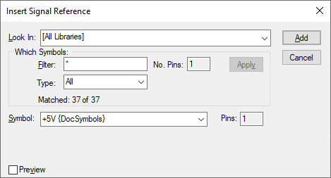
Look In
Use this to choose a documentation symbol library to search for the required signal reference. The library list is set up in Library Folders in the library manager. Two special entries exist:
Use [All Libraries] to choose from symbols in all of the documentation symbol libraries. If the same symbol is in more than one library, the first found will be used, so library order is important.
Use [Current Design] to choose from the signal references already added to the design.
If the Vault is in use, the drop-down list will additionally include Vault entries. Each Vault folder that contains documentation symbols will be listed and the special entry [Vault Only] allows all signal references from the Vault to be exclusively viewed.
Which Symbols
Use the Filter box to enter a string containing the ”*” or ”?” wildcard characters to filter the list to only matching names e.g. “A*“. Use the No. Pins box to limit the matching symbols to those of a set number of pins (blank means any pin count). press Apply to alter the list of names accordingly. The number that matched the filters is shown in the dialog.
Symbol
This listbox contains the symbol names to choose from. Select the one required. The number of pins on the selected symbol is displayed in the Pins box.
Type
This dropdown allows you to select SCM Doc Symbols that have been saved or created using a Type. From the list, you can choose from All, Bus Reference, Net Label, Page Link, All and Signal Reference. This enables you to refine the selection for the type required at the time. Other SCM Doc Symbol types are added through their own menu item on the Insert menu.
Preview
Use this to optionally display what the symbol will look like when added to the design.
Interactively Positioning A Signal Reference
Whilst using the mouse to position the symbol you can use the shortcut menu (shown below) to change its angle and mirror it, amongst other things. This is explained in detail in the Move operation.
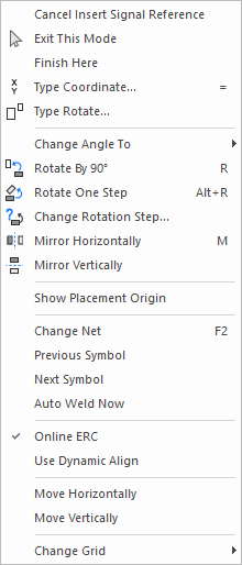
Use Cancel Insert Signal Reference to cancel the current item being added and return to the dialog.
or
Use Exit Mode to cancel the current item being added and exit back to Select Mode.
or
Click to drop the symbol at the required position.
Creating Pointers and Net Labels
Both Pointer Symbols and Net Labels are created using an inserted Text Callout attached to the Pin Terminal. The Text Callout text is given the Net Name attribute using an Attribute substitution. Using this feature enables the text box to be dynamic; adjusting the box to a proportional length of the Net Name within it.
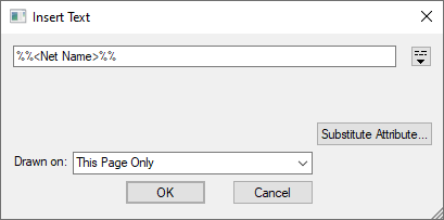
Once positioned, the Text Callout shape is then formatted using the Text Callout Properties page.
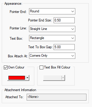
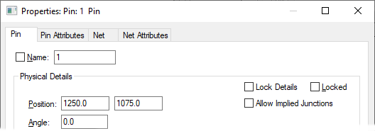
For the Pin, under Pin Properties, it is recommended that the Allow Implied Junctions switch is set off to override general design settings.
Both symbol types would then be saved using their respective Doc Symbol Properties.
- Pointer: Type - Signal Reference
- Net Label: Type - Net Label
Related Topics
Properties - Documentation Symbols | Bus Ref Symbol | Net Label Symbol | Page Link Symbol | Testpoints | Mounting Holes | Star Points | Branch Points | Block Ports| Block Symbols | Text Callout | Text Callout Properties | Pin Properties | Doc Symbol Properties