Insert Connection is used to connect two or more items within a design.
Shortcuts
Default Keys: None
Default Menu: Insert
Command: Insert Connection
Locating this option
Available from: Insert menu > Connection option
How To Use Insert Connection
Activate Insert Connection mode by one of the following:
- Under Insert on the Menu Bar, select Connection, or
- Select the Insert PCB Connection icon from the PCB Toolbar, which by default is positioned down the left side of the design window, or
- Use an assigned shortcut key.
Making the Connections
Having activated Insert Connection mode, add the connections as follows:
- Select the start point for the connection by clicking the mouse. This must be on an electrically connectable point, such as a pad, track or piece of copper.
- Select the end point for the connection by clicking the mouse, again on an electrically connectable point.
- The system will continue inserting further connections as part of the same net. You may complete the current net by double clicking rather than single clicking to finish the connection, or alternatively, once you have made the final connection for the net, press Esc on the keyboard or right click the mouse and select Cancel Insert PCB Connection
- You may now click to start another connection on a new net or if you have finished adding connections, exit Insert Connection mode by pressing Esc on the keyboard, by right clicking the mouse and selecting Cancel Insert PCB Connection or by selecting an alternative command from the Toolbar or Menu.
Note:
A new net will be allocated a default net name of the form $1, $2, $3 etc.
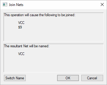
If you are connecting to an existing net you are presented with the following warning:

The net being added will be merged into the net to which it is connecting.
Typing the Component Pin Names
Instead of selecting pins with the mouse, it is also possible to type the pin name by using the Type Pin Name command available from the context menu during Insert Connection. More information about this mode is detailed here.
Changing the Connection Options
You may right click to display the context menu of options available while inserting a connection. This includes options to Change Net and to Mark the Net.
Connections and Power Planes>
Connections that connect to a power plane are displayed differently on surface mounted pads to that of normal connections connected to through hole pads. This is displayed when the Technology Layer is defined as a Bias of Power Plane and with a nominated plane Net. The connection is then displayed as a butterfly or bowtie as shown below:
