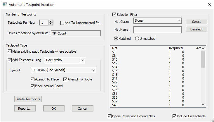
This command allows the addition of testpoints so that each net gets the required minimum number of testpoints for automatic testing.
Shortcuts
Default Keys: None
Default Menu: Tools
Command: Auto Insert Testpoints
Locating this option
Available from: Tools menu > Auto Insert Testpoints option
How to use Auto Insert Testpoints

The left side of the dialog controls how many testpoints and what type of testpoints are to be added. The right side of the dialog enables you to select which nets the testpoints will be added to.
Number of Testpoints
The initial value for the number of testpoints is that defined at the design level in the Testpoint Rules, or the last used value.
Testpoints Per Net
Specify the minimum number of testpoints required on the selected nets. You may have specified a minimum in the Testpoint Rules. If either of these values is 0, then no testpoints should be added to these nets. Otherwise, the maximum value from the net class or attribute and the value in the dialog is used.
Add To Unconnected Pads
When checked, Add To Unconnected Pads will add a testpoint to each component pad which is not connected to a net.
Unless redefined by attribute
If the Unless redefined by attribute displays a Net Attribute, then this attribute and value will be used instead of the Testpoints Per Net entry above. This name is defined in the Testpoint Rules dialog of your Technology using an attribute and value that would have been added to the net using Net Properties. The attribute name will be defined in Attribute Names and will be a usage of Net.
Testpoint Type
Make existing pads Testpoints where possible when checked, utilises existing pads on the design, as long as they obey the Testpoint Rules. This option is used in preference to adding new testpoint design items.
Add Testpoints using type specifies the type of design item for new testpoints. The available types are the same as those when manually adding a testpoint. For Free Pad and Via you will need to specify the Pad Style to use and for Part or Symbol, the Part or Doc Symbol to use.
You can Attempt to Place and Attempt to Route these testpoints once they are added. Otherwise they are placed around the board, ready for placement (Part and Symbol testpoints can be added to the component bin).
List of Nets
The list of nets on the right side of the dialog shows which nets require more testpoints. If you do not have the Selection Filter enabled, testpoints will be added to all listed nets. With the Selection Filter enabled (using the check box), testpoints are only added to the selected nets.
You can Select and Deselect nets based on the filter criteria. Both the Net Class and Net Name can be wildcard strings, and you can select either Matched or Unmatched nets. Note that the filter is only used to change the selection, it is the selected nets which testpoints are applied to.
You can choose to Ignore Power and Ground Nets by checking the box, this removes these nets from the list.
You can choose to Include Unreachable testpoints by checking the box. Excluding these would mean that previously placed testpoints, which are unreachable according to the current rules, would not be included in the count, so additional testpoints would be required.
Delete Testpoints
Press this button to delete all the existing testpoints which are not marked as Locked against automatic removal. Once they are deleted, you are returned to the dialog so that you can add new ones. Testpoints which were passed from the schematic design should not be unlocked, because these should only be deleted or added through the Synchronisation process.
Report
Press the report button to get a summary of which nets will have testpoints added.
Related Topics
Testability rules | Design Settings - Testpoint | Insert Testpoints