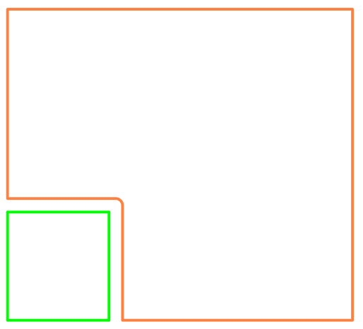
The Cut Shape option can be used to cut a shape in the design into many shapes by drawing a line that separates them.
Multiple selected shapes can be cut with the same line at once. this feature is particularly useful if you wish to create a split power plane by cutting a Template.
When cutting shapes that belong to a net, such as Copper, the nets of the resulting shapes can be specified.
Shortcuts
Default Keys: None
Default Menu: Edit
Command: Cut Shape
Locating this option
Available from: Edit menu > Cut Shape option
The items Cut Shape can be used on
Cut Shape can be used on all electrical and documentation shapes. The shapes can be Closed or Open. The cut line can be Closed to create new shapes within a cutout of the original shape.
Electrical shapes that belong to a net such as copper or templates can also be cut. When doing so, the spacing distance specified in the design rules will be used to set the width of the cut line. This width can be overridden, although it may result in a design rule error. Through prompts, you are able to change the net(s) that the resulting shapes will belong to.
Poured copper cannot be cut.
Restrictions apply when cutting multiple shapes at once, these shapes must:
- All be of the same type.
- Not be a cutout of another shape.
- Not be a controlled shape such as a spline, spiral, ellipse or wave.
- If multiple electrical shapes are selected for cutting they must belong to the same net.
Context Menu Options
When using Cut Shape, there are options available that are specific to this mode on the context menu when you right click:
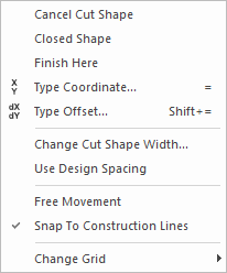
- Closed Shape - Select this option to make the resultant shape closed. This is useful for creating a shape within a shape.
- Use Finish Here to finish the shape editing, or use double click.
- Type Coordinate can be used to set the coordinate location of the next corner.
- Type Offset can be used to offset the next corner by the value typed.
- Change Cut Shape Width - Available on all shape types. Use this to set the width of the line used to cut the shape, this determines the gap distance between the resulting shapes. If the width is set to zero (0), the resultant shapes will overlap on their centre (cut) lines.
- Use Design Spacing - Available for electrical shapes (Copper, Templates etc.). Select this to use the Design Spacing Rule of the item being cut, for example Copper to Copper spacing. This spacing will be used instead of the Cut Shape Width.
- Free Movement - Cut Shape is locked to 45 degree segment mode. If you wish to use any angle, select this option.
- Snap To Construction Lines - Construction Lines can be used to guide the cut of the shape. This mode can be toggled on and off. With it off, the Cut Shape option will use the grid. When using a grid, it will snap to points on the Construction Line that are in line with the grid axes.
- Change Grid - select the grid you wish to use if not using Construction Lines.
The Cut Shape Line Width
There are a number of cut line widths that can be used (as free widths or Spacings):
- User defined as a shape width, This can be either zero size or a defined size. Zero width aligns the centre lines of the resultant shapes coincident on top of each other, or as a width, which creates a gap. The gap is also taken between the centre lines.
- When using a Spacing rule width, the gap is taken between the edge of the shapes.
How to Cut a Shape
-
Select the Cut Shape option and select the shape(s) to cut.
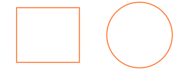
Optionally pre-select the shape(s) you wish to cut then select Cut Shape.
-
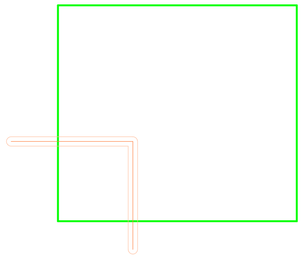
Click to start the cutting line, or drag and drop a straight cutting line.
-
Continue clicking to add vertices to the line, double-click to finish the line and make the cut.
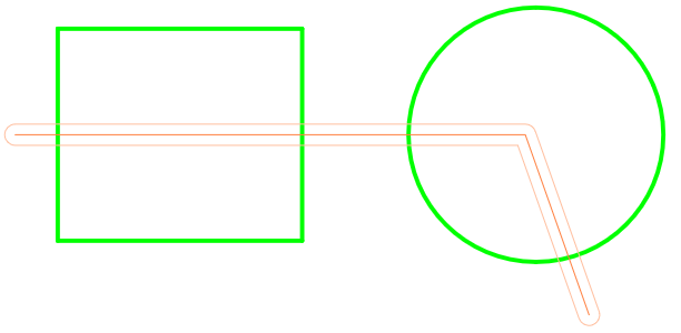
-
The resulting shapes are left selected, this is ready for another cut if you wish.
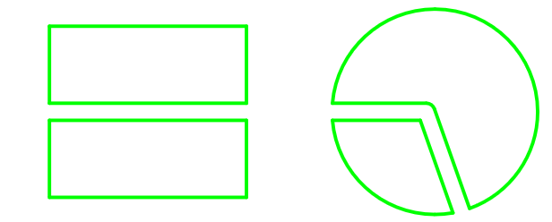
Cutting an Electrical Shape
-
Select the Cut Shape option from the Edit menu.
-
Choose or type in the name of the net that the new shape will be.
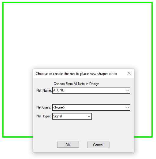
-
Click to start the cutting line, or drag and drop a straight cutting line.
-
Continue clicking to add vertices to the line, double-click to finish and make the cut.
-
If the cut results in two shapes, you can confirm if the highlighted shape is the correct one to place on the new net and choose the other shape if not.
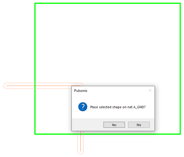
-
If the cut results in multiple shapes you will be prompted to add each new shape to a net in turn.
-
After cutting, the new shapes will be checked against the design rules, you will be notified if they cause an error.
-
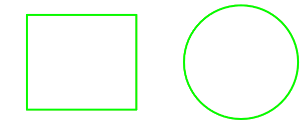
The resultant shapes appear like this:
