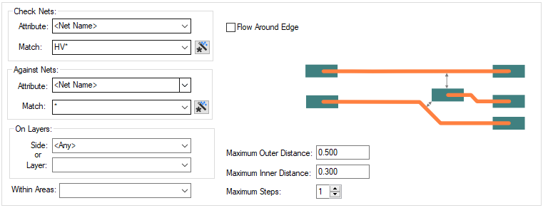
The Creepage Rules dialog is used to specify the rules used when creepage needs to be defined and subsequently checked. The purpose of the check is to report where the total surface gaps could allow creepage between two nets, either directly or through third party copper. You can also check creepage around board edges or cutouts. You can limit this check to a specific layer or named area.
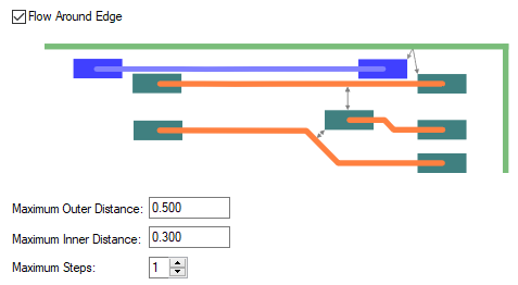
Creepage is caused by current flowing through pollutants on the surface of a board, this is typically increased with higher voltages. The creepage check finds gaps between critical nets between which current could flow. Third party copper can conduct current, meaning that the creepage can accumulate in several steps or jumps between the two critical nets. As this flow is across the surface of the board, the distance can effectively be increased by cutting a slot in the board, the creepage distance then follows the lip of the board edge. An unplated hole with drilled out pad can also be used as a slot. Current can also flow around the edge of the board in the third dimension, so changing layers. Although typically less of a problem, creepage can occur across inner board layers. There are therefore two values for the maximum creepage distance - Outer and Inner, which are then combined to give the final result.
The general rule matching mechanism is described here.
Shortcuts
Menu: Setup
Default Keys: T
Command: Technology
Locating this option
Available from: Setup menu > Technology option > Rules - DFM/DFT - Creepage page
Using the dialog
On selection, the Technology dialog opens, select Creepage Rules. The existing Creepage Rules for the Technology being used will be presented.

Navigation
The buttons to the right side of the dialog are used to navigate the grid, the general common buttons are detailed on the Technology Navigation page.
Using the editing pane

A rule defines two nets. Each is defined using a net Attribute Name and a Match Value. The
Match Value can be a wildcarded. In particular, you can
match the inbuilt attributes
Check Nets
Attribute
Define the first net based item you wish to use in your Rule. This can be explicit or the name can use a wildcard match.
Against Nets
Define the second net based item you wish to use in your Rule. This can be explicit or the name can use a wildcard match.
On Layers
You can decide whether to run the rule on a specific Side: or Layer: selected from the drop down list selections provided. If you wish to run the rule on all layers, either define Side as < Any>, or Layer: as * to indicate all layers.
Within Areas
If you have any Areas defined in the design, a rule can be defined for a specific named area. Rules can be defined for any combination of Layers and Areas, as required. If the check is limited by area, then the two ends of the step must be within an area, but the step may be across areas edges, and the edge of the area is not followed (unlike a board edge).
Flow Around Edge
Check this box to allow layer changes by flowing around the edge of the board in the third dimension (the board edge includes board cutouts). This does not prevent flow around the lip of the board edge in the layer plane.

Maximum Outer and Inner Distances

Maximum Outer Distance
The maximum total distance for which creepage would cause a problem on the outer surfaces of the board. This includes the distance around a board edge. This distance around the board edge can include changing layers, as well as around the lip of the edge. A value of 0 means that no creepage distance is checked on an outer layer.
Maximum Inner Distance
The maximum total distance creepage would cause a problem on inner layers of the board. This value is typically less than the Maximum Outer Distance. This does not include any layer changes as these can only be done on the outer edges of the board. A value of 0 means that no creepage distance is checked on an inner layer.
Combining Inner and Outer Distances
Each step will contribute to the total inner or outer distance. The inner and outer distances are combined in proportion to their respective maximums. If the total percentage does not exceed 100%, then there is an error. For example: Maximum Outer Distance = 2mm, Maximum Inner Distance = 1mm; actual total outer distance = 1.5mm (75% of maximum), actual total inner distance = 0.3mm (30% of total); total percentage = 105% so there is no error.
Max Steps
The maximum number of steps between copper. One step means a single gap between the two nominated nets. Two steps means that an intermediate piece of copper is traversed.
Export and Import CSV
Use the Export CSV button to export the data in your PCB design into a CSV format file. Using the Export CSV option will provide you with a formatted template ready for you to edit in your own data.
Use the Import CSV button to import data back into the PCB design using a CSV format file.
The data in the file represents a spreadsheet of dialog contents with the data headings along the top row.
Units
The Units button allows you to locally switch between Metric and Imperial units whilst in this dialog. Once the dialog is closed, the units revert back to the original design units. If switching to different units to the design units, the value typed will be converted when you next enter this page.
Rules Checking
The Creepage rules can be checked using [Design Rules Checking
- Creepage](../tools/idh_drc.md#adjacentnets). These can be viewed using the DRC Errors Bar.
Related Topics
Technology Overview | Using Dialog Grids | Net Name | Layers | Areas | Technology Rules | Wildcard Matches | Design Rules Checking | Options - Warnings | Net DRC Errors Bar | Colours - Text Warnings Export CSV | Import CSV