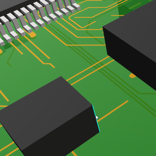
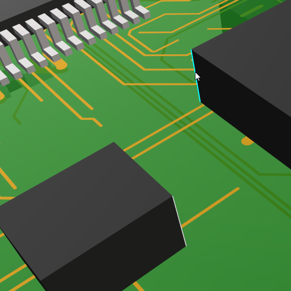
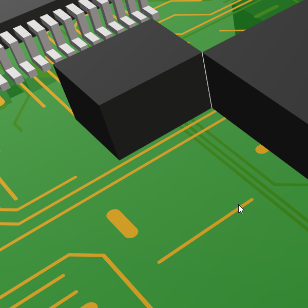
The Align option, available in the 3D Viewer and STEP model positioning in a Footprint. This option allows for the snapping of one 3D item onto another, for example, the STEP model to the footprint.
Shortcuts
Default Keys: None
Default Menu: 3D Design
Command: Align
Locating this option
Within the 3D Viewer, it is available from: 3D Design menu > Align button


Using Align
Note, to use this option, you must have Components and/or Enclosures selectable in the STEP 3D View Settings - Interaction dialog.
Selecting Align will initiate align mode, a message in the status bar will instruct you to select the item to be aligned.
By default in align mode, the selection mode is such that sub-parts of a 3D object, such as a particular face, edge or corner may be selected as the point from which to make the alignment. Furthermore, any combination of these sub-parts can be aligned, meaning that, for example, one shape’s face can be aligned with another shape’s edge.
Once the first item is selected, the outline of said selection is highlighted white and the status bar will then instruct you to select the second item that you wish to align the first item to. Doing so, will complete the alignment and the first selected item will snap to second selection.
Pressing the Esc key while align mode is active will exit without applying any alignment.
Any change in position that takes place as a result of alignment will be reflected in the STEP output if the Write STEP file option is used. If you have the Automatically Synchronise 2D option enabled then the orientation and/or position of the corresponding component on the originating PCB will be updated.