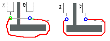
Sketch Track option gives you the ability to quickly draw in your approximate routing path and then uses a simple routing algorithm to automatically convert it to tracks on the current grid, tidied up and avoiding design obstacles. This option would be used as an alternative to Insert Track
Shortcuts
Default Keys: None
Default Menu: Insert
Command: Sketch Track
Locating this option
Available from: Insert menu > Sketch Track option
Sketch Track Procedure
Sketch Track option can be found on the Insert menu . When started the cursor will change to the sketch cursor for the duration of the operation.
Click on the item you wish to route from, or pick on an unrouted connection to route. The picked item will be highlighted and a track drawn from the item to the cursor.
Move the cursor to sketch a track along the approximate path required. Right click to use the shortcut menu at any stage to change the sketch track preferences. These are described in more detail below.
When you move over an item you can finish the sketch on, the cursor will change to show an ‘F’ to indicate that a left click will finish the track on that item.
Click on the target item to finish on, or click in space to end with a dangling track. A tidy route will replace the path you sketched avoiding any obstacles you sketched too close to. If you clicked to finish in space you will then carry on sketching until the next point is defined.
If you are editing an unrouted connection, a dynamic highlighted connection will be drawn to the target pad. You may use double click in this case to finish the dangling connection automatically. The equivalent function is on the shortcut menu called Complete.

Sketch Track Options
The sketch router operation is controlled using several options. Some of these have switches found in the Edit Track page of the Options dialog, on the Tools menu. All can be found on the shortcut menu during sketching.
Change Layer
Before starting the sketch, use Change Layer to set the layer that you wish the track to be on. This layer is used if the picked item to start from reaches it, otherwise the layer the start item is on will be used.
Once sketching, use it to change the current routing layer that the sketched track segments are on, or to change the complete track to a new layer. If not in Point To Point mode (explained later) and Use Any Layer is off (explained layer) and some segments have already been sketched a Via will be introduced at the cursor position. This way a path can be sketched on through several layers.
The default layer provided to change to will be the layer previous to the last layer change. This makes it easy to toggle between two electrical layers whilst laying down track segments.
A quicker way to change layer is to use Control Left Click. This will swap the layer to the other side without the need for a dialog.
A set of commands are also available to change the layer of the track directly to an electrical layer. Use Change To Layer 1 to change to the top electrical layer, Change To Layer 2 to change to the next electrical layer and so on. If you want to use these commands regularly, you can associate them with shortcut keys using customise. For example you could assign layers 1 to 10 to keys 1 to 10, and layers 11 to 20 to keys shift + 1 to shift + 10.
If Draw Current Layer On Top in the Display Options is set, the picture will be redrawn to show all items on this layer on top.
Use Default Style
This is only available prior to starting the sketch once Sketch mode has been started. If you choose to override the Default Track style by using Change Style from the context menu, you can change the width of the track back to the default style by selecting this option. The style on the Status bar is cleared to indicate that the track style will be defaulted as follows:
If there is a default Net Class or a rule defined in Net Styles for new nets, the default track style is the nominal width on this, otherwise the default track style is taken from the Net styles defaults. If the track is started on an item that is already on a net, the track style will be inherited from that style.
Change Style
Use Change Style to change the width of the whole sketched track to a specified value. This value will be used even if the picked item is already on a net. The new style is shown on the status bar.
Change Net
Change Net is normally used to change the name of a new net when adding new tracks to the design. If you rename to an existing net’s name, the nets will be joined.
Mark Net
Use to highlight the whole net that you are editing in the Marked Net colour . This can make it easier to see which pads to finish new tracks on. This option is a toggle, and so using it again will remove the highlighting.
Show/Hide Breakouts On Net
If adding a track and no breakouts are currently displayed, use the Show Breakouts On Net option from the shortcut menu to show all the potential breakout paths on the net. If the option is not on the menu, there are no breakouts on the net.
You can end on any of these breakouts and the path from where you picked on the breakout to the breakout pad will be copied to create a track to finish your sketch. Once displayed, the option changes to Hide Breakouts On Net.
End Track On Via
Use to sketch a stub route out from a SMD pad to a via, just like Insert Track. The via will be shown at the end of the sketched track.
Use Any Layer
Leave unchecked to restrict the tidied routing path to only use the layers that the sketch was made on. If checked, it can use any electrical layer in the design (except power plane layers).
Sketch On Grid
With this checked the sketched track will lock onto the current Track Grid rather than be freehand. You may find this gives you a better indication of the final track path by putting the track onto a grid to start with.
Mitre Result
When the sketched track has been converted to the correct track path, any orthogonal corners will be mitred. This option will use the Min and Max Mitre sizes set up in the Auto Mitre dialog on the Tools menu.
Point To Point
A slightly different way of working within sketch mode using a click and “Route To Here” method rather than a follow this sketch method. If this mode is chosen, you will place the end of a dynamic connection instead of sketching a track path. This mode is explained in more detail below.
Show Connection To Net
The Show Connection To Net option is only available if you did not select an unrouted connection when starting the sketch. This switches on or off the ability to show a dynamic connection to the closest item on the current net being edited. Use it to enable use of Complete when you are close to the required item that you wish to end the track on.
Show Finish Markers
The Show Finish Markers option switches the display of the finish markers on and off. Use finish markers to indicate when you are over an item that you can finish on.
Allow Join Nets
With the Allow Join Nets option selected you will not be able to join nets of different net names. Use it to ease the picking of items to finish the track on by not being able to pick items on other nets.
Change Grid
When the sketched track is being converted to the correct track path it places the tracks on the current grid. Use this sub-menu to choose which grid you wish to use for this result. It allows you to change the grid step and whether the grids are visible or not. See the Change Grid help page for more details.
Be aware that changing the grid in this option, or in any other manual track option, will change the grid used for interactive editing of tracks throughout the entire program.
Finishing the Route
There are several ways of finishing the sketch and producing the required route. The obvious is to left click on the item you wish to end the track on. Alternatively you can right click to use the finish options at the top of the shortcut menu.
Finish Here
Use this to complete the sketch at the current cursor position, and produce a track to this point.
Complete
This is available when there is a trailing highlighted connection to a target item. For this to happen you must have either selected an unrouted connection to start the sketching on, or are using the Show Connection To Net option.
Using this option will first add a correct track to the current cursor position, and then complete the task by adding another track path to the item at the end of the dangling connection. Alternatively, double click can be used to quickly achieve this.
Finish On Via
This option will finish the sketch on a via at the current cursor position. Use it to sketch a stub route out from a SMD pad to a via.
Sketched Loop Removal
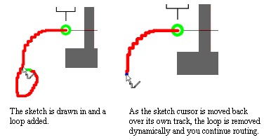
Loop removal is not an option but is enabled permanently. It will remove accidental loops created whilst sketching tracks. This is more easily demonstrated in the illustration below:

This is useful when selecting connections to route, as a sketch is drawn from the connection source pad to the cursor position and is probably not where you want the track to go. By moving the cursor to the source pad the sketch will be removed (as a loop) and started again from the pad. You are then free to sketch your path to the target pad.
Point To Point Mode
Although the Point To Point mode is part of the Sketch Track option, it is really an alternative way of working to quickly add routes to the design.
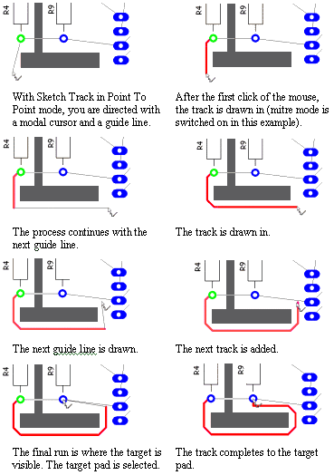
The principle is that of telling the track to “follow me”. You click to add a target point and a track will be added from the previous corner (or start pad) to the new point avoiding the obstacles as it goes. The difference between this and the sketch mode is the track path is not constrained to the path drawn, and can go anywhere in order to reach the gridded position nearest to the target point.
The illustrations below show the sequence of adding a simple track around an obstacle.

Breakouts
You can you start or end the sketch on a breakout path from a pad. The breakout pattern will be copied from its pad to the gridded point that you picked on it, converted to tracks and vias, and inserted between the pad and the sketched track you are adding. All vias will be changed to use the “best fit” via span calculated from its attached tracks.
The tracks created from breakout paths are absolute and are not part of the sketch to be converted into tracks by this option. Therefore, since the aim of the Sketch Track option is to quickly create error free track paths, you will not be able to start or end on a breakout if the track generated from the breakout is in error.
Related Topics
Adding Vias | Breakouts | Insert Connection | Insert Track | Change Layer | Change Track Style | Options | Show Connection To Net | Show Finish Markers