Use this page to set the properties of pins in the part. Properties such as assigning the mapping of PCB Footprint pins to the part, mapping can include alphanumeric pin numbers too. Pre-assigned Net Names, Pin Type, Pin Networks and additional attributes can be added to pins to give them special and enhanced characteristics.
Locating this option
Available from: Library Manager option > Edit button > Parts tab > Pins page
How to Use This Page
There is one line in this grid for each pin in the part. This includes pins that belong to gates, as well as signal pins that only exist at pin level. All the pins are brought together here to make it easier to set up information related to all the pins.
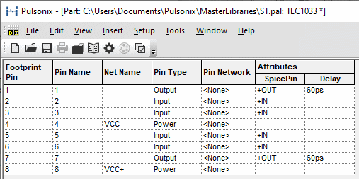
Footprint Pin
This is the footprint pin’s sequence number, and is not an editable field.
Pin Name
The pin name is usually visible on Schematic Drawings and is used in the PCB netlist. This name may be a number, or alphanumeric (for example, A1, B1, etc.). Changing the name of a pin that belongs to a gate will automatically update the corresponding cell on the Gates Page.
Apply Increment to Selected Cells
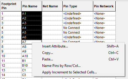
You can quickly enter alphanumeric pin names by entering the first name, for example “A1”, and then dragging the mouse to select that cell and some cells below it. Then right click to use the Apply Increment to Selected Cells option. The selected cells below “A1” will be named “A2” onwards.
Name Pins by Row/Col
For some components, notably grid based components such as Pin Grid Arrays (PGA) and Ball Grid Arrays (BGA), the pins are named based on their row and column positions on the PCB symbol and have names like A1, A2, B1, B2 and so on. The Col. option, available from Tools on the main menubar, or from the right click context menu for a cell in the Pin Name column of the grid, allows this type of pin naming pattern to be quickly generated and also allows for gaps in the naming sequence.
Net Name
Any pin on the part may be assigned a Net Name. When the part is used to add a component to a design, these pins are automatically connected to the designated net. This feature is generally used to specify the power and ground pins of components, but may be used for any predefined nets to which the pins must be connected.
Pin Type
Choose the required pin type from the drop-down list. The list will contain the pin types defined in the Technology data.
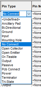
Power and Ground pin types have a special meaning. They will cause the pin to be connected to a Power or Ground type net when the part is used to add a component to a design. If there is more than one net of the appropriate type defined in the design, you will be prompted with the Select Signal for Pin dialog for which net to use. The net type is defined on the Net Class.
Pin types are used in a schematic design for Electrical Rule Checking and can be overridden in the schematic design with local values.
Match Pin Types
You can use the Match Pin Types option from the Tools menu to automatically allocate
pin types for any pins that are marked as
Pin Network
You can add a Pin Network to the pin. A Pin Network defines one or more components which must be connected to the pin when the part is used in a design. The network could therefore be used for bypass capacitors or termination resistors. The definition of the Pin Network is stored in the technology. Only the name of the network is stored in the part. It is therefore not necessary to create the pin network in the technology at this stage. However, any pin networks already defined in the current technology will be offered in the drop down list.
Attributes
The columns to the right of Pin Type are used to show the attributes attached to the pins, with each column sub-heading showing an attribute name. Initially, when a part is first created, no attributes column is visible as it is only displayed once the first attribute is added.
To add a new attribute name to a pin, use the Insert Attribute option. This option is available from the main menu bar, the toolbar, or from the shortcut menu. If a new attribute name is specified a new column will be displayed to show the assigned values.
To add or edit a pin’s attribute value in an existing attribute column simply click on the grid cell and edit the value.
Connectors
Connector Parts do not have a Gates page, so the Pin Swap and Symbol exceptions are defined through additional columns on the Pins page.
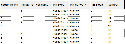
By selecting the Symbol Name in the column, you can change the name of symbol for a different one, for example, Pin 1, using the Change Symbol option.
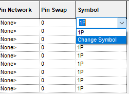
On selection, you are presented with the Change Gate Symbol dialog from where you can select a new symbol.
Once a new symbol is used, the drop down list will then display the Reset Symbol option. This enables you to reset the symbol back to the original symbol.
Pin Swap
Connectors do not have a gates page, so the pin swap information is supplied in the Pin Swap column on this page.
Symbol
This column defines the symbol to be used on each pin on a connector. The default symbol is defined on the details page, but you can override the default with an explicit symbol. Click on the cell and use Change Symbol to define another symbol for the selected pin. If the default symbol has been override, you can change it back to the default by selecting Reset Symbol.
Using Copy and Paste To Edit Values
The values in this grid can be manipulated using the normal Copy and Paste techniques associated with spreadsheet applications such as Microsoft Excel. This includes the ability to copy and paste multiple rows and/or columns of data.
For more information on using copy and paste in a Part Editor grid see the Gates Page.
Pasting Values into the Grid
When data is pasted into grid the values are subject to the normal constraints of the column into which they are being inserted. Any invalid values will not be inserted. For example, a value pasted into the Pin Type column must be one of the predefined Pin Types shown in a Pin Type cell dropdown list.
The Footprint Pin column is read only and as such may not have values pasted into it although it may be selected and copied.
Importing Pin Data from other sources
It is also possible to import values for the pins from external files using the Import Pin Data option .
Related Topics
Parts Editor | Gates Page | Technology - Net Class | Technology - Pin Networks | Technology - Pin Types | Insert Attribute