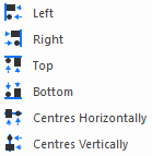
Align is used to adjust the position of selected design items so that their sides, centres or origins are horizontally or vertically in line. It may also be used to align shape segments, whole items or to align linear dimensions.
Shortcuts
Toolbar: 
Command: Align Left
Command: Align Right
Command: Align Top
Command: Align Bottom
Command: Align Centres Vertically
Command: Align Centres Horizontally
Command: Align Origins Vertically
Command: Align Origins Horizontally
Default Keys: None
Default Menu: Utilities
Locating this option
Available from: Utilities menu > Align > options
Aligning Items in a Design
There are 3 ways of using these options depending on what you currently have selected when one of the align tools is used.
- Pre-select the items that you want to align with each other and use the Align tool as a single shot operation.
- Pre-select a single item that you wish to use as the master to align other items to. Then use the Align tool to pick items to align to this master item.
- Do not pre-select anything. Use the Align tool to select a master item and then pick items to align to it.
Using the Align Tools
-
Select one of the Align functions from the Utilities menu, or use one of the shortcuts mentioned above.
-
You are now in one of the Align modes, by clicking the right hand mouse button you will see the Align shortcuts menu:

Select the type of alignment required. The appropriate cursor for that mode will be used.
You may use the “Type Coordinate” dialog from this menu to select an alignment position by typing the required coordinates, or to choose a master item by typing a component or pad name. For example, “U1” or “U1.8”.
-
If a single item was pre-selected, it will be used as the master item to align against. If nothing was selected, you will be prompted to choose the item to align to. Single click to pick the master item, or click in space to specify a gridded position to align to. Use the shift key to select a whole item, or use the Ctrl key to force select of a position even if the cursor is over an item.
If a master item was selected it will be drawn in the highlighted colour. An alignment guide line will be drawn in the select colour through the point that will be used for alignment. The actual coordinate that defines this horizontal or vertical line is shown on the status bar. If a master item was picked, its details will also be shown on this bar.
-
You will now enter the alignment phase of the operation. Single click on the part of an item that you wish to align. The item will be moved so that it lies on the alignment guide line. Use shift click to align whole items.
If you pick a single shape segment, it will attempt to move just that segment to the alignment position.
If you pick either side of a linear dimension, it will stretch the picked side of the dimension to reach the alignment position.
You can pick multiple items to align at this stage by using the Ctrl key when you pick, or by dragging the mouse to frame around the items to align. If the Ctrl key was used to select multiple items, left click on one of the selected items to perform the alignment. Note that Frame Select and Polygon Select are available from the shortcut menu.
-
Use the shortcut menu at any stage to change the alignment mode, or pick an item using the “Type Coordinate” dialog. This dialog can be used to select items by typing their positions, or selecting components and pads by typing their names.
-
When you have finished aligning items press the Escape key. You may now select a new master item, or press the Escape key again to exit the Align option.
Align Example
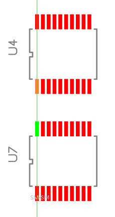
The following example shows alignment of two components by using their pad positions. The alignment mode used in the example is “Align Centres Vertically”.

First select the lower left pad on the top component as the master item. This could be done with a left click on the pad, or by using the “Type Coordinate ” option by typing “=U5.1”.
The pad will be highlighted and a vertical line will be drawn through its centre showing the alignment position.

Next select the lower left pad on the bottom component to align it as shown. Again this could be done by using left click, or by typing “=U6.1”.