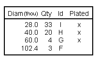
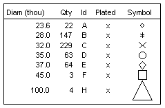
A drill table shows the number and sizes of the drills used for a given layer span. It also shows the drill letter to be used and if the hole is plated.

Shortcuts
Default Keys: None
Default Menu: Insert
Command: Insert Drill Table
Locating this option
Available from: Insert menu > Drill Table option
How to use the dialog

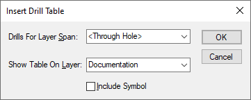
Before placing the drill table in the design, you must specify which
Layer Span the table applies to (you will normally have a
You must also specify what Layer you want the drill table to appear on (this would often be a non-electrical layer which would be combined with a drill drawing during plotting).
Lastly, check the Include Symbol box if you have different symbol shapes for each drill size, and you wish to include these shapes in the drill table for reference.

When you press the Add button, a drill table will be generated and you can position the table where you want on the design. Once the table has been placed you return to the dialog, where you can add another table or Cancel the dialog.
Note that a Drill Size Table inserted on to a Drill Drawing layer will automatically take on the Layer Span associated with that layer and only list types of Drill Holes displayed on that layer.
The drill table is of a fixed format, and cannot be edited. The units used to show the drill diameter are defined in the Drill Size Table dialog. If you modify the design (by adding or deleting some of the drill holes), the drill tables may need updating. This is automatically done when you create any plots, but can be done at any time using the Update Drill Tables option.
It is also possible to insert a generated drill report using Report Maker. This enables you to create a custom drill table to your own requirements. For example, you may wish to add additional horizontal or vertical lines to separate the drill symbol information.
Related Topics
Technology - Layer Span | Technology - Drill Size Table | Update Drill Tables | Plots