Use this option to insert construction lines or circles into a design or symbol.
These constructs do not represent a physical part of the design, but are infinite lines (or semi-infinite) and circles that can be used to aid placement of design items, or used to construct accurate shapes, tracks or breakouts by following a path through construction line intersects. They are always drawn as a single pixel wide line and therefore do not use a line style.
There are a set of modes and options for creating construction lines based on existing design items. For example to create lines along existing segments, bisecting segments, dividing angles, through arc centres and tangents, through any two points, etc.
This makes it easy to construct lines that cross at required positions, like the centre of a triangle or centre of an arc for example. It also allows the laying down of guide lines, relative to a start point, that match exact line angles and offsets taken from a drawing to make it easy to construct an accurate complex shape.
Construction lines do not get in the way of normal design work as they can be placed on separate layers, are easily hidden and do not take part in design bounding box calculations, or frame select operations. They are never plotted through CAM Output, but will feature on any printing pages if visible.
Note: If you are displaying grids as lines they can obscure horizontal and vertical construction lines. In this case it is advisable to use the Design Option to draw grids underneath the actual design items.
Shortcuts
Default Keys: None
Default Menu: Insert
Command: Insert Infinite Construction Line
Default Keys: None
Default Menu: Insert
Command: Insert Construction Spline
Default Keys: None
Default Menu: Insert
Command: Insert Construction Circle
Default Keys: None
Default Menu: Insert
Command: Insert Construction Ellipse
Default Keys: None
Default Menu: Insert
Command: Insert Construction Wave
Default Keys: None
Default Menu: Insert
Command: Insert Construction Rectangle
Default Keys: None
Default Menu: Insert
Command: Insert Construction Triangle
Default Keys: None
Default Menu: Insert
Command: Insert Construction Polygon
Default Keys: None
Default Menu: Insert
Command: Insert Construction Line
Locating this option
Available from: Insert menu > Insert Construction option
Construction Line Types
Depending on how they are added, and how they are used, Construction Lines can one of three types:
- Infinite lines - where both ends are infinite and end outside the design area.
- Non-infinite lines - these start and end within the design.
- Semi-infinite - where one end is infinite and the other end ends in the design. For example, a circle divided by 3 Construction Lines where the end point of the lines is the centre of the circle.
Where You Can Use Construction Lines
Construction lines can be simply used as visible guide lines to see if items are in line, or can be used by options to add shapes, or snap items onto exact positions.
-
In Align you can align items using a construction line.
-
When using Add Polygon you can create a shape by using Use Construction Regions to merge together shapes defined by their surrounding construction lines.
-
When editing a shape you can create a shape by using Follow Construction Lines to automatically place segments exactly on construction lines.
-
In the Insert Shape functions you can snap the points in a rectangle, circle, triangle, line or polygon onto construction lines, or onto the intersection of construction lines using the Snap To Item option.
-
When adding a track or breakout you can create a path by using Follow Construction Lines to automatically place segments exactly on construction lines.
-
The above three methods can also be used when creating cutouts in shapes, or when merging shapes together.
-
When a shape is selected you can use Edit Shape Using Construction Regions. available from the context menu (right click). This allows you to add or remove the regions enclosed by construction lines to the selected shape.
-
After adding a track or shape by following construction lines, you can alter the shape by moving a corner and using the Snap To Construction Lines option to keep the corner on construction lines.
-
You can use multiple horizontal and vertical construction lines to define a irregular matrix of points to be used as a grid in Move when using its Snap To Construction Lines option. This makes the construction line intersection points act as magnets to attract the moving item when it is near to them. If the item is not near to a construction line it is gridded normally.
The snap distance that is used to determine if the moving item is close to a construction line, uses the value defined in the Placement Sites option.
Using construction circles or ellipses for this enables you to define irregular polar grids.
-
You can position an origin at the intersection of two selected construction lines or circles using the Set Coordinate Origin, Set Relative Origin and Set Symbol Origin commands.
-
Dimensions can be snapped to and attached to construction lines.
-
With segments selected, use the Add Construction Line Along Segment or Segments option to add Construction Lines to complex shapes.
-
Cut Shape has a context menu option to enable snapping to Construction Lines.
Copying a Construction Line
You can use Duplicate on a previously selected construction line, or use Ctrl Drag on an existing construction line to add another.
This will add the new line at the same angle as the selected line and highlight the original. As you move the line an offset will be shown on the status bar from the original. You can use the context menu whilst moving it to alter its angle, or use the Type Offset command to place the line at an exact offset from the original (positive offsets will offset the new line by the specified offset on the same side of the original line as the cursor is currently positioned).
While inserting or copying a Construction Line, if you right click, you can select the Add Mirrored Line option from the context menu. This will automatically add another line the other side of the selected line (as well as the one you are currently adding). As you move the current line, the other ‘mirrored’ line will also move.
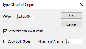
When one Construction Line or two perpendicular Construction Lines are selected, the Copy with Offset option is available on the context menu. This allows parallel lines to be created at a specified offset from the original line. When used with 2 selected lines, it can form a grid of equal spacing using the lines by selecting the Number of Copies to use. If the Copy Both Sides check box is selected, it will copy the number of Steps selected both sides of the original selected Construction Lines.
How To Insert a Construction Circle
There are three ways to create a new construction circle in a design as follows:
-
On the Insert menu, select Construction Line then select Circle. You can add an icon for this command to the toolbar if you wish.
Then proceed to add a circle using the standard Insert Circle procedure.
-
Use Duplicate on a previously selected construction circle, or use Ctrl Drag on an existing construction circle to add another.
-
Use the Add Construction Line option, choose the Along A Segment mode, and select an existing arc or circle in the design to create the circle that passes through it. This is described in more detail below.
How To Insert a New Construction Line
On the Insert menu, select Construction Line then select Infinite Line. You can add an icon for this command to the toolbar if you wish.
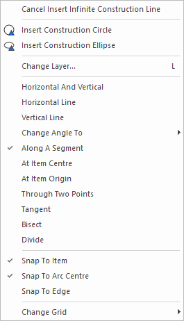
You will now be in the Add Construction Line option, indicated by one of its special modal cursors, waiting for you to select the appropriate point or design item to define the position of the required line. There are several different modes of defining construction lines, as described below, and you will initially be placed into the same mode as was last used. The modal cursor and the text on the status bar will indicate the mode you are currently in.
Right click to use the context menu to choose the mode for defining the construction line.
Snapping To Design Items
Whatever mode is being used, when selecting a position for the construction line to pass through there are two options available to snap the selected point onto an existing design item.
Check the Snap To Item option on the context menu to force the selected point be snapped to the closest part of the item beneath the cursor. If snapping to a construction line, the snap point will be further refined to use a construction line intersection point if one is near.
If Snap To Item is being used, check the Snap To Arc Centre option to cause the construction line point to snap to the centre of a selected arc, rather than the nearest point on it.
If the Snap To Arc Centre option is not being used, and an arc or circle is selected whilst adding a construction line, the selected point on the arc will first try to snap to the top, bottom, left or right most point on the arc if it is close enough. If this fails it will try to snap to the tangent point where the line would touch the arc (again if close enough to the selected point). Otherwise it will snap to the nearest point on the arc.
If Snap To Item is being used, check the Snap To Edge option to cause the construction line point to snap to the nearest edge of a selected item, rather than its origin or the nearest point on its centre line if it is a segment.
Horizontal And Vertical
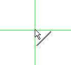
This mode adds two construction lines at once, shown as horizontal and vertical lines through the cursor position. Click to select the required position for the intersection of the lines. The new lines will be added to the design and drawn in the highlight colour. The next two construction lines will appear, showing the offset from the intersection of the highlighted lines on the status bar.
Single Construction Line
The next three modes, Horizontal Line, Vertical Line and Change Angle To, add a single construction line at a specified angle through the selected position. As each line is added, it is highlighted and the next line is displayed on the cursor using the same angle as the previous line. The status bar shows the distance from the highlighted line.
 �
�
 �
�

Use the Change Angle To sub-menu to alter the angle of the line currently being added. The menu shows all the thirty degree steps commonly used, or use the Enter Angle option to type the exact angle required. You can also set the construction line angle to match any straight line segment already in the design. Do this by using Ctrl Click on the existing segment. The moving line will change its angle to the selected segment, and if the segment was a construction line it will be highlighted and the status bar altered to show the distance from it.
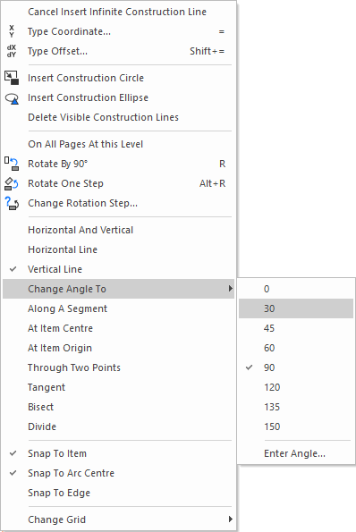
Use the Rotate By 90 option if you want a line that is perpendicular to the current line angle.
If a previously added construction line is highlighted you can use the Type Offset option to set the exact distance from it for the line currently being added. Positive offsets will offset the new line by the specified offset on the same side of the original line as the cursor is currently positioned, negative offsets will offset the new line on the ‘far side’ of the original one.
The line being added moves on the current chosen grid, which can be changed using the Change Grid option on the context menu. If a highlighted line is shown, you can use the Grid The Offset option to change the gridding so that the moving line moves in exact grid steps away from the highlighted line. This enables you to place two lines exactly a set amount apart, and is especially useful when adding angled lines.
If you have a construction line pre-selected, or have used Control Click on an existing construction line, or if you are duplicating an existing construction line, you will be able to automatically add a copy of the current line being placed, mirrored about the original line. To do this select the Add Mirrored Line option from the context menu. You will see two dynamic parallel lines being moved either side of the original line. If you type a fixed offset, it will be applied to both dynamic lines either side of the original.
Along A Segment
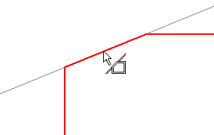
This mode allows you to create construction lines, or construction circles, that travel along the centreline of the selected shape or track segment, or along the edges of selected pad shapes. Each time you select a segment in the design, a construction line, or circle if an arc or circle is selected, is added to the design. This can be useful if you want to recreate the construction lines that were used to create a complex shape, and then use them to correct, or alter the shape.
 �
�
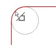
This mode can also be used on lines and arcs that form the edges of pad shapes. Using this it is easy to add a circle that is the exact size of a round pad.
When using the Along A Segment mode, if a segment is used to draw the construction line, pressing the N key will toggle between which side of the segment the construction line is placed on. In this mode, if a corner is used to draw the construction line, pressing the N key will toggle between the four sides of the two segments connecting to the corner instead.
Through Two Points
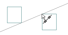
This mode allows you to define a construction line that passes through two selected points, usually used with Snap To Item checked to snap to two specific points on items in the design.
This is a two stage process as follows:
- Click to select the first point for the construction line to pass through.
- A dynamic line will be drawn from the selected point to the current cursor position, and the status bar will show the current angle of the moving line.
- Click to define the second point, and the construction line will be constructed through the two selected points and added to the design. You are now ready to add the next line.
 �
�
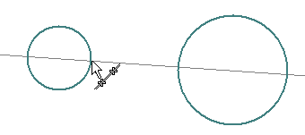
Tangent
This mode helps you create a construction line that is a tangent to a selected arc or circle from a selected point.
This is a another two stage process as follows:
- Click to select the segment arc or circle for the construction line to become a tangent to.
- A dynamic line will be drawn from a tangent to the selected arc, to the current cursor position, and the status bar will show the current angle of the moving line. If the cursor position is within the arc sector the tangent is drawn at the point where a line from the arc centre passing through the cursor position touches the arc.
- Click to define the point that the tangent is to pass through. The construction line will be constructed from the selected items and added to the design. You are now ready to add the next line.
- If you want to add a tangent between two circles, first make sure that Snap To Item is on and Snap To Arc Centre is off. Then select one of the circles, and move the cursor close to the required tangent point on the other circle. Click again and the selected point on the second circle will be adjusted to the actual tangent point.
- Use Change Angle To to set the exact angle of the tangent, and then finish.
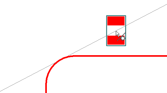 �
�
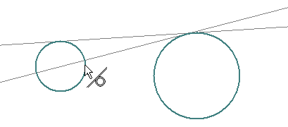
When using the Tangent snap feature there is an option in Options, Interaction where the tangent drawn will jump to the nearest 90 degree line on the arc/circle selected.
Bisect
Use this option to add a construction line that bisects an angle, or bisects the line between two points.
If an angle is to be bisected follow this procedure.
-
Check the Divide Angle option on the context menu. The cursor will change the show you are dividing an angle.
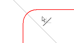
-
You can click on an existing arc segment to immediately bisect its angle. In this case the construction line will be added and you will be ready to bisect another line.
-
You can click on an existing straight line segment to define the first line for the angle to be bisected. A temporary line will drawn through the selected line.
-
Now select the second line of the angle. A construction line will be added bisecting the angle between the two selected lines. If the selected lines are parallel then the space between them is bisected. You will now be ready to select the next angle to be bisected.
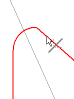
If you are creating a bisecting line perpendicular to the line between two points, follow this procedure:
-
Uncheck the Divide Angle option on the context menu in order to indicate it is a line you wish to bisect rather than an angle. The cursor will change the show you are not dividing an angle.
-
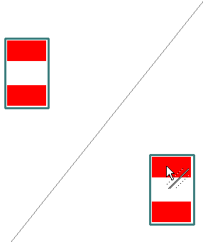
Check the Divide Perpendicular option on the context menu to indicate the angle of the resultant line is to be perpendicular to the line between the selected points.
-
You can use Ctrl Click on an existing straight line segment to immediately bisect it. In this case the construction line will be added and you will be ready to bisect another line.
If you wish to set this feature to always use the Ctrl key mode, there is an option in Options, Interaction to set it on. With it set on, it can be overridden using the Ctrl key while selecting the segment.
-
If not using the Ctrl key, click on an existing point to define the first point on a line to be bisected. A temporary line will drawn through the selected line, perpendicular to the moving cursor.
-
Now select the second point. A construction line will be added perpendicular to, and bisecting, the line between the two selected points. You will now be ready to select the next points to be bisected.
If you are creating a bisecting line between two points at a fixed angle, follow this procedure:
-
Uncheck the Divide Angle option on the context menu in order to indicate it is a line you wish to bisect rather than an angle. The cursor will change the show you are not dividing an angle.
-
Uncheck the Divide Perpendicular option on the context menu. The bisecting line will use the current angle displayed on the status bar.

-
Click on an existing point to define the first point on a line to be bisected. A temporary line will drawn through the selected line at the current angle.
-
You can use Ctrl Click on an existing straight line segment to change the angle of the bisecting line to the same angle as the selected line.
-
Now select the second point. A construction line will be added at the current angle, bisecting the line between the two selected points. You will now be ready to select the next points to be bisected.
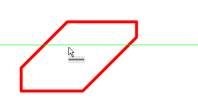
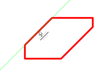
The Bisect and Divide features can be affected when the Options switch Use Angle from Selected Segment is set. Select this option to default to using the angle of the segment if a point on a segment is selected.
With the mode off, the line will be drawn horizontally or vertically:
With the mode on, the line will be drawn along the segment selected:
Divide
This option uses the same interactive procedures as the Bisect option above, but adds multiple construction lines to divide the angle or line into multiple parts. When the option is chosen, the following dialog is given to get the number you want to divide by. If you are already in the Divide option, select the Change Divide By option from the shortcut menu to change the divide number.

If you are using the Divide Angle option you can also click on a circle or round pad to immediately divide it into segments. A dialog will be presented to get the angle of the first dividing line in the circle.
When the construction lines are added to divide the selected angle or line, unlike Bisect, lines will also be added at the extents of the angle or line.
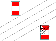
You can use Ctrl Click on an existing angled line segment to divide it. In this case the construction line will be added and you will be ready to select another line.
If you wish to set this feature to always use the Ctrl key mode, there is an option in Options, Interaction to set it on. With it set on, it can be overridden using the Ctrl key while selecting the segment.
Dividing a Circle by odd numbers
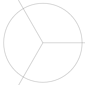
If you wish to divide a circle by an odd number; 3, 5, 7 etc,. lines are added that meet in the centre of the circle but which extend outside the design area (to infinity).
Delete Visible Construction Lines
When adding a Construction Line, use the Delete Visible Construction Lines option from the context menu to remove any other Lines apart from the one you are adding. They will be deleted regardless of the layer they appear on provided they are visible.
You can also choose the Delete Visible Construction Lines option from the context menu with nothing selected in the design.
Alternatively, you also have the option, Delete Construction Lines on Layer under Edit using the context menu with a Line selected in the design. This will delete all Lines that are on the same layer only as the one selected.
Change Layer
This option is only available if the construction line is in a PCB Design, PCB Documentation Symbol or Footprint. Use it to change the line being added to a new layer. See the Change Layer help page for more details.
At Origin and At Centre options
For a selected shape, you can add Horizontal and Vertical Construction Lines at the Origin and Centre using the options from the context menu:
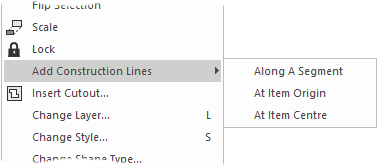
Along A Segment Along A Segment (described above).
At Origin will select the origin from where the item was created.
At Centre will use the centre of the item or the centre of the bounding box if the item is an irregular shape.
Named Construction Lines
You may wish to name Construction Lines in order to identify them. Use the Properties dialog on a selected Construction Line to do this. Named Construction Lines can be located using the Find Bar.
Edit Shape Using Construction Regions
There is an option for adding regions to or chopping regions out of a selected shape. With the shape selected, the option can be accessed from the context menu, Edit Shape Using Construction Region. This mode works with Construction Lines with any sequence of straight or arc segments.
This means that one Construction Lines are added to and around shapes, the shape can be modified based on regions without having to manually select segments, move them and snap to the Construction Lines.
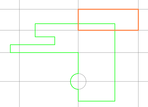
Once the Edit Shape Using Construction Region option is selected from the context menu of a selected shape, a selection region indicator is displayed. This will be either a solid shape to indicate the shape will be modified outwards, or a dotted region shape to indicate the shape will be modified inwards. If the shape can only be modified in one direction, then only the solid indicator is shown. Some regions cannot be selected because they might create self-intersecting shapes.
Below are two examples, showing the two styles of region modification:
| Shape modified outwards (showing region as a solid line): | Resultant shape: | |
 | 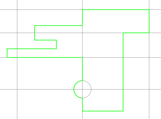 |
| Shape Modified Inwards (showing region dotted): | Resultant shape: | |
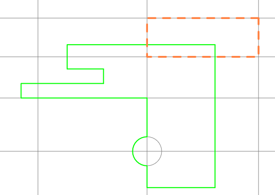 | 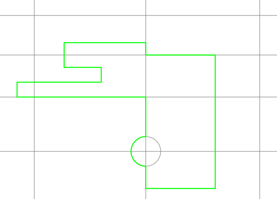 |
Add Construction Line Along Segment or Segments
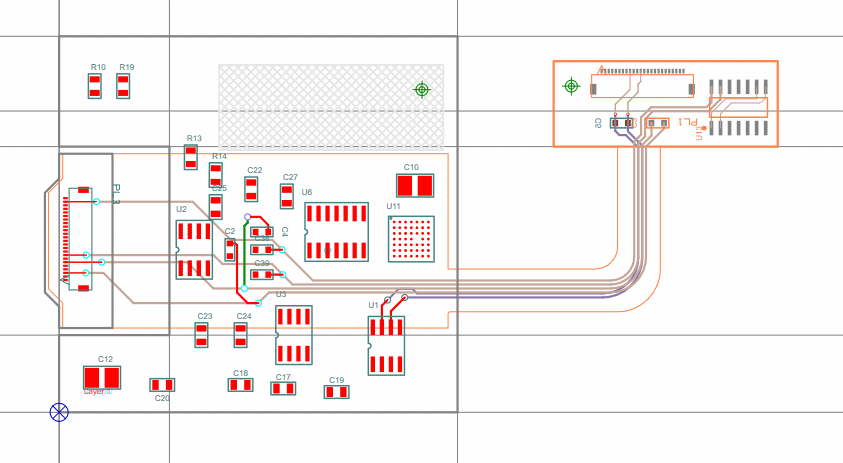
With a shape segment or segments selected, from the context menu, you can add Construction Lines along these segments. This will add infinite lines along those selected segments. This option means you can quickly add multiple, and often complex, construction lines to a shape from where you can modify the shape using other interactive features, such as Edit Shape Using Construction Lines.
Clip Construction Line
You can clip construction lines using the Clip Construction Line option. More can be found here on using it.
DXF Import
You can also create construction lines through the DXF Import mechanism.
Related Topics
Clip Construction Line | Add Cutout | Add Polygon | Align | Change Layer | Duplicate | DXF Import | Editing Shapes | Adding a Track | Grids | Merging Shapes | Move | Inserting Shape | Options, Interaction