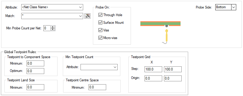
The Testpoint Rules dialog is used to specify how nets should be tested.
The general rule matching mechanism is described here.
Shortcuts
Menu: Setup
Default Keys: T
Command: Technology
Locating this option
Available from: Setup menu > Technology option > Rules - DFM/DFT > Testpoint page
Using the Testpoint Rules dialog
On selection, the Technology dialog opens, select Testpoint Rules. The existing Testpoint Rules for the Technology being used will be presented.

Navigation
The buttons to the right side of the dialog are used to navigate the grid, the general common buttons are detailed on the Technology Navigation page.
Using the editing pane

The appropriate testpoint rule is found for each net by working down the list of rules until the first match
is found. Hence, the order of the rules is important. A match is when the specified Attribute Name and
Match Value match attributes of a net. So the net must have the given attribute, and it’s value must
wildcard match the value. In particular, you can match the
inbuilt attributes
Add a testpoint rule using the New button, which will create a row in the table.
The Probe Side defines which side will be used for board testing for the matching net.
When Inserting a Test Point, the Probe Side restricts which side a Test Point can be inserted on. There is also a Design Rule Check for Unreachable Test Points. This checks that the test point is physically reachable from it’s Probe Side and that it’s Probe Side coincides with the technology Probe Side.
Probe Side is either Top, Bottom or All (Either) side.
You can define which types of items can be used as a Test Point in the Test On section.
You can specify the minimum number of Probe points required on the net.
Global Testpoint Rules
Testpoint to Component Space
The Minimum space between a Testpoint and any body area of any Component on the probe side.
The Optimum spacing is used by the Testability Report and is used as a warning for potential testpoints which are close to components.
Testpoint Land Size
The Testpoint Land Size is the minimum size of the pad on the probe side. This ensures that the pad is large enough to be correctly probed. A value of 0 effectively means no limit is defined.
Min Testpoint Count
If you enter an attribute name here, then the value of this attribute on each net is used as the minimum testpoint count. No value or not numeric value means no minimum specified, a value of 0 means no testpoints required on this net.
Testpoint Centre Space
The Testpoint Centre Space is the required spacing between testpoint centres. This ensures that testpoints are far enough apart to be probed correctly. A value of 0 effectively means no check will be performed.
Testpoint Grid
The Testpoint Grid is also shown on this dialog. You can edit this grid on the Tools Grid tab. You can effectively turn off the grid by making the step 0.
Export and Import CSV
Use the Export CSV button to export the data in your design into a CSV format file. Using the Export CSV option will provide you with a formatted template ready for you to edit in your own data.
Use the Import CSV button to import data back into the design using a CSV format file.
The data in the file represents a spreadsheet of dialog contents with the data headings along the top row.
Units
The Units button allows you to locally switch between Metric and Imperial units whilst in this dialog. Once the dialog is closed, the units revert back to the original design units. If switching to different units to the design units, the value typed will be converted when you next enter this page.
Related Topics
Insert Testpoint | Using Dialog Grids | Testability Report | Grids | Tools Grid | Automatic Testpoint Insertion | Specctra Interface - Testpoints | Design Rule Check | Export CSV | Import CSV