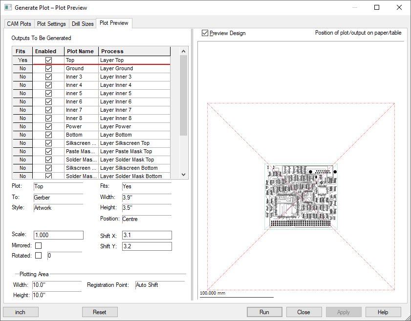
This page allows you to preview the positioning and scaling of each of your plots on the relevant output medium. It also provides you with a Preview of the plot expected and its anticipated relative position to the plot ‘bed’.
Locating this option
Available from: Output menu > CAM Plots > Plot Preview tab
Using the dialog

Outputs to be Generated
The Outputs to be Generated list shows all the plots currently available. Click on any of these to see a Preview of the plot in the right-hand pane (provided the Preview Design check box is selected).
All plots currently Enabled will be plotted when the Run button is pressed. You can Enabled or disable plots by clicking the check box on the row for each plot.
Preview Design
The Preview Design check box above the preview allows you to turn on the detailed preview.
The image that is displayed in the preview will depend on the kind of output device for the plot and the type or style of the plot. It is not intended as a complete preview of the entire plot contents, but as a visual representation on the selection and positioning of items being plotted.
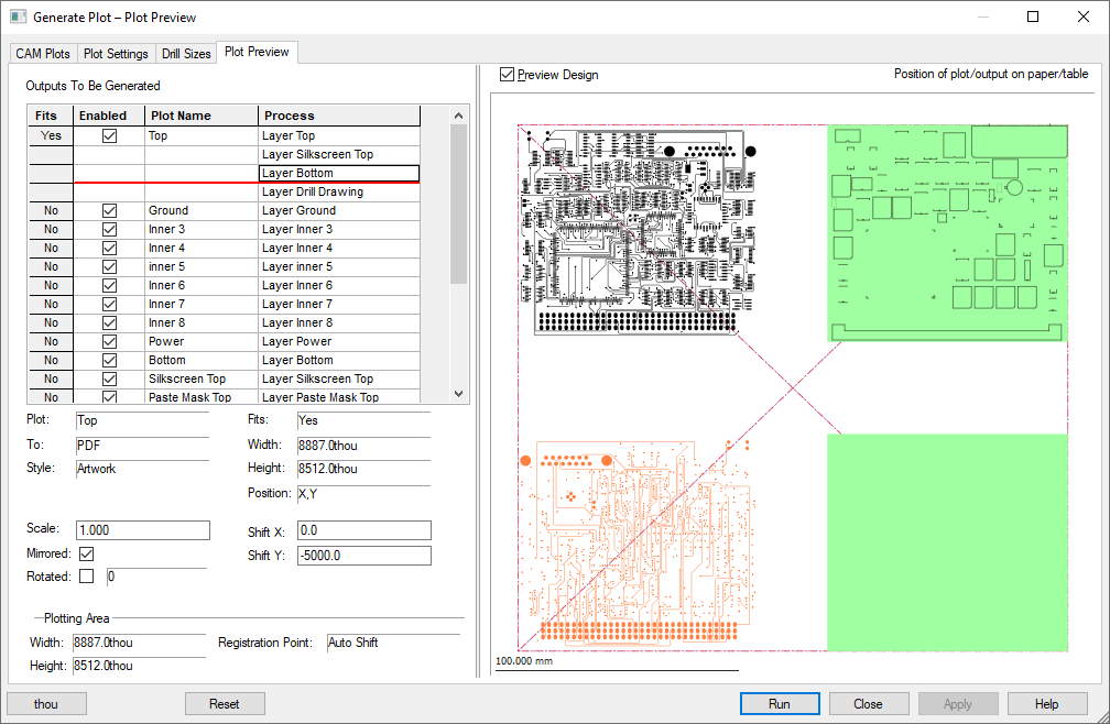
The red area shows the plotting area (paper or plot table), the blue area shows the area of the plot that is to be positioned onto the paper. The green area indicates the board outline (in PCB).
If you select an additional plot, the items on that plot will be highlighted so you can see where it is relative to the main plot.
Note that for windows output, the size of the plot area excludes the margin.
Plot Summary
Below the list of plot names is a summary of the actual parameters to be used for the currently previewed plot. Along with confirmation of the plot name selected, it shows if the plot fits onto the device plotting area and the width and height of the final plot. The units used will be those defined in the Plot Settings and Output Device dialog but can be changed here using the units button at the bottom left corner of the dialog. You can change the displayed units between Metric and Imperial. This will help you check that the plot will fit on the media you are plotting to.
For regular plots, the summary presented will inform you of crucial information, such as the Plot Name, whether it Fits the plot bed, Plot Type and Plot Style etc. Advanced transformations and multiple plots plotted on the same bed can also be achieved. Normally, other parameters, such as the Scale will be defined in the main CAM Plots dialog. However, some fields are editable to make adjustments to the plot or plots as required.
The Plotting Area shown is for information only and cannot be edited.
Plotting and Previewing Multiple Plots
Fields can be edited to transform the position of individual plots (where more than one has been defined using the Add To Plot option). You can edit the Scale, Mirrored, Rotated, Shift X & Shift Y values on this dialog. Equivalent values will be set on the original plot where multiple plots are defined.
The Reset button at the bottom of this dialog is used to cancel any pending edits.
The transformation is given relative to the Plotting Area Registration Point (hence the Shift X & Y will be different values to those specified on the CAM Plots page, which give the registration point relative to the design origin.)
Where multiple plots have been defined using the Add To Plot option, the currently selected plot will be highlighted in orange. The original plot that the others are based off will be shown in black.
The Shift X & Shift Y values can be defined positively or negatively, depending on how you require the plot to be shifted on the bed relative to the original plot.

Related Topics
CAM Plots | Plot Wizard | Auto Generate CAM Plots | Plot Settings | Drill Size Table | Output CAM Plots | Print