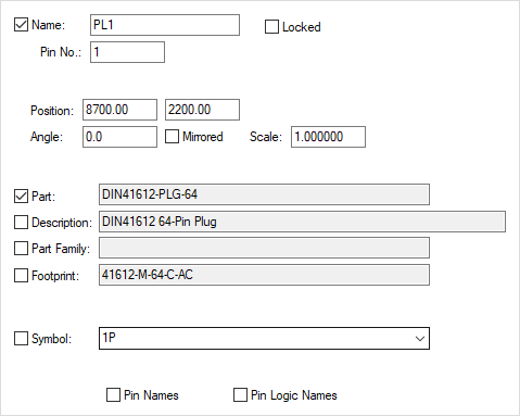
This dialog is displayed when the Properties option is chosen with a single pin of a schematics connector component selected.
It shows and allows you to modify properties for the selected Connector Pin.
Shortcuts
Default Keys: I or Alt+Enter
Default Menu: Edit
Command: Properties
Locating this option
Available from: Edit menu > Properties option
Available from: Context menu > Properties option
Available from: Shortcut key > I
Using the Connector Pin Dialog

Name displays the reference name of the component. You can use this to change the reference name of the component. If you try to change to a connector pin that already exists in the design you will prompted to see if you want to swap the pins. If you select no then no swap will take place. If the component does not exist in the design you will be prompted to see if you want to add this component. If you select yes then this connector pin will be moved to the bin, and a new component will be added with the corresponding pin on this component replacing this pin. The remaining pins of the new connector component will be added to the bin.
Pin represents the pin number within the connector component. You can change this to another pin number within the component. This will cause either the connector pins to be swapped in the design or be moved into and out of the component bin. Changing both the name and pin will work in the same way as changing the name.
Position is the coordinates of the connector pin on the page. This can be used to move the connector pin on the page.
Angle is the rotation of the connector pin. This edit control can be used to change the rotation.
Mirrored indicates whether the connector pin has been mirrored about the y-axis. Checking or unchecking this causes the mirroring to change.
Part is the name of the part that the component is an instance of. Checking the control to the left will display the part name on the connector pin. You cannot change the part name from here. Use Properties - Component to change the part.
Footprint indicates which footprint associated with the part will be used when the schematic is transferred to PCB. Checking the control to the left will display the footprint name on the connector pin.
Symbol is the name of the symbol that represents the connector pin. Checking the control to the left will display the symbol name on the connector pin.
Checking Pin Names will cause the pin name to be displayed on the pin.