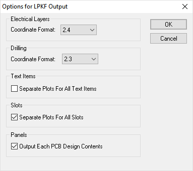
This dialog is used to define various settings related to the generation of files for the LPKF system.
Locating this option
Available from: Output menu > LPKF option > Setup
How to use this dialog

Electrical Layers
Choose the format of the leading and trailing zeros from the drop down list for the electrical layers output.
Drilling
Choose the format of the leading and trailing zeros from the drop down list for the drilling output.
Text Items
Text items can be plotted in two different ways. To plot them as normal items on each plot along with other items from that layer, leave the check box clear. Depending on the text you have on your board, this can produce an ‘untidy’ result:

To counteract this, you can plot text items separately by setting the check box. This will result in two additional layers being created in the output file for each plot that contains text, and text items being omitted from the other layers.

Once processed using the appropriate steps in LPKF CircuitPro and CircuitCAM, the resulting plot would then look something like this:

Slots
Slots are non-round holes and can be plotted in two different ways. Check the box to plot plated and unplated slots on their own separate layers within the output file. Leave the box unchecked to include plated slots with the plated drill holes, and to include unplated slots with the unplated drill holes.
Panels
The Output Each PCB Design Contents check box is only shown if you are producing output for a Panel Design. Use it to specify that each PCB item in the panel will be replaced by the full contents of its PCB design file. Leave it unchecked if you are just producing a quick check panel output and only want to output the items you see in the PCB instances in the panel design.