This dialog is displayed when the Properties option is chosen with a Construction Line selected.
It shows and allows you to modify properties for the selected Construction Line items.
Shortcuts
Default Keys: I or Alt+Enter
Default Menu: Edit
Command: Properties
Locating this option
Available from: Edit menu > Properties option
Available from: Context menu > Properties option
Available from: Shortcut key > I
Using the Shape Properties Dialog
Name
A Construction Line can have an optional name. The box is checked if the name is visible. Note that it will only be visible on screen if the ‘Item Name’ attribute is also set to displayed in the Colours dialog. The name can be used to find the Construction line with the Find Bar.
Type
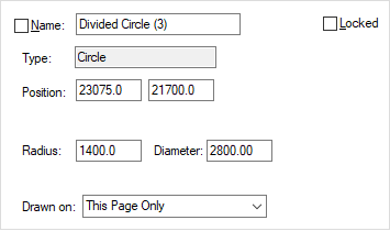
This is the type of construction line selected. The following dialog is shown for a circle (in a Schematic design):

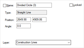
The dialog shown for a straight line is as follows (and is shown for a PCB design):

The Position, Angle and Radius of the construction lines are shown in the current design units. For a circle, the position is at the centre.
Drawn on
In Schematics, you can define which pages the construction line is Drawn On. Use This Page Only to specify it is only drawn on the current page. Use All Pages In Design to draw the line on every page within the design. Use All Pages At This Level to draw the line on all the top level pages within the current block.
Layer
In PCB designs, you can change the Layer the construction line is on by selecting another layer from the dropdown list.
Locked
To make the shape Locked against changes, check the Locked box.