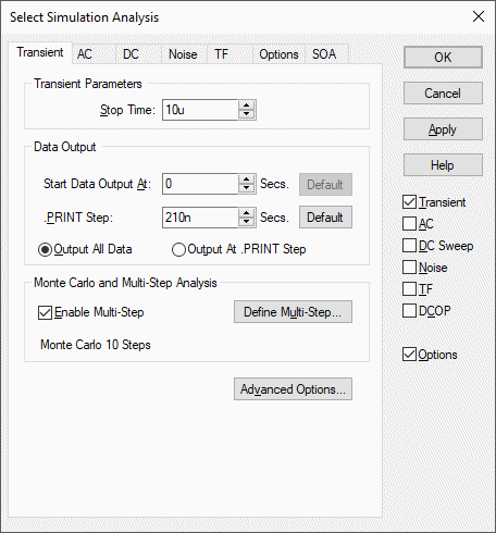
This page can be found on the Simulation Parameters dialog. Use it to set up simulation for transient analysis.
Transient analysis is the most useful and general analysis mode. First the bias point is found. Then the circuit is simulated over a fixed time interval in steps of varying size according to circuit activity. The circuit may contain any number of time varying voltage and current sources to simulate external signals, test generators etc.
Shortcuts
Default Keys: None
Default Menu: Simulation
Command: Simulation Parameters
How To Setup Transient Analysis Parameters
Select the Simulation Parameters option from the Simulation menu and pick the Transient tab.
The following page will be displayed:

Transient Parameters
Stop Time - This is the time after which the simulation stops.
Note that the simulation can be paused before the stop time is reached and the results so far examined. It is also possible to restart the simulation after the stop time has been reached and continue for as long as is needed. For these reasons, it is not so important to get the stop time absolutely right. You should be aware, however, that the default values for a number of simulator parameters are chosen according to the stop time. (The minimum time step for example). You should avoid therefore entering inappropriate values for stop time.
Data Output
Sometimes it is desirable to restrict the amount of data being generated by the simulator which in some situations can be very large. You can specify that data output does not begin until after some specified time and you can also specify a time interval for the data.
Output All Data / Output At .PRINT Step
The simulator generates data at a variable time step according to circuit activity. If Output All Data is checked, all this data is output. If Output At .PRINT Step is checked, the data is output at a fixed time step regardless of the activity in the circuit. The actual interval is set by the .PRINT step. This is explained below.
If the Output At .PRINT Step option is checked, the simulator is forced to perform an additional step at the required interval for the data output. The fixed time step interval data is not generated by interpolation as is the case with generic SPICE and other products derived from it.
Start Data Output At
No simulation data will be output until this time is reached.
.PRINT Step
.PRINT is a simulator command that can be specified in the netlist to enable the output of tabulated data in the list file. See the Pulsonix-Spice Users Guide for details of .PRINT.
The value specified here controls the interval used for the tabulated output provided by .PRINT but the same value is also used to determine the data output interval if Output At .PRINT Step is specified. (see above).
Monte Carlo and Multi-step Analysis
Transient analysis can be setup to automatically repeat while varying some circuit parameter. See Multi-Step Analyses for details.
Advanced Options
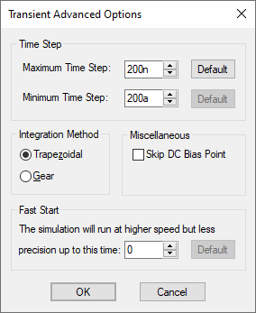
Press this button to alter some of the less commonly changed transient analysis parameters. The following dialog will be displayed:

Time Step
The simulator increases the time step when there is little or no circuit activity. The simulator always chooses the time step it uses but it will not rise above the maximum time step specified here. Press the Default button to reset it to the default value.
If the simulator needs to use a time step smaller than the minimum specified, the simulation will abort. Reduce this value if the simulation aborts with the message “Time step too small”. This might happen for long runs on circuits that have very small time constants.
Integration Method
Set this to Gear if you see an unexplained triangular ringing in the simulation results. Always use Trapezoidal for resonant circuits. A full discussion on integration methods is given in the “Convergence and Accuracy” chapter of the Pulsonix-Spice Users Guide.
Skip DC Bias Point
Usually, transient analysis is preceded by a bias point calculation. This option forces it to be bypassed. You should only select this in special circumstances. If checked, the simulation will start with all nodes at zero volts. Note that unless all voltage and current sources are specified to have zero output at time zero, the simulation may fail to converge if this option is specified.
Fast Start
The accuracy of the simulation will be relaxed for the period specified. This will speed up the run at the expense of precision.
This is a means of accelerating the process of finding a steady state in circuits such as oscillators and switching power supplies. Its often of little interest how the steady state is reached so precision can be relaxed while finding it.
Note that the reduced precision can also reduce the accuracy at which a steady state is found and often a settling time is required after the “fast start” period.
Restarting Transient Analysis
A transient analysis that has run to completion may be continued beyond its original stop time using the transient restart feature. Select schematic menu Simulation | Restart Transient then enter the new stop time.
Related Topics
AC Sweep Analysis | DC Sweep Analysis | Multi-Step Analyses | Noise Analysis | Simulation Parameters | Sweep Modes | Transfer Function