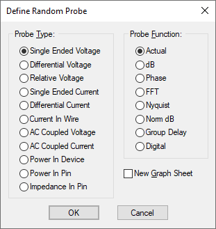
Use this dialog to change the type and function of the probe being used by the Random Probe tool.
How To Change The Probe Type
When using the Random Probe tool, right click and use the User Defined Probe option from the shortcut menu.
The following dialog will be displayed:

Not all voltage or current functions will be available for each type of probe. When you select a probe type, only the functions suitable for that type will be enabled. There follows some notes about some of the types and functions.
Impedance
You may plot the AC impedance at a circuit node. This only works in AC analysis. This works by calculating V/I at the device pin selected. Because currents are only available in voltage sources, inductors, resistors and capacitors with AC analysis, you must select a pin of one of these devices to find circuit impedance.
Power In Device
This works by calculating the sum of VI products at each pin of the device.
Note that, because Pulsonix-Spice is able to find the current in a sub-circuit device, it can also calculate such a device’s power. Be aware, however, that as this power is calculated from the VI product of the device’s pins, the calculation may be inaccurate if the sub-circuit uses global nodes.
Actual
This is the default function for the probe type. The voltage or current is plotted without using a function.
Phase
Plots the phase of the voltage or current in degrees in a continuous output i.e. it does wrap from 180 degrees to -180 degrees.
dB
Plots 20 * log10(magnitude(voltage or current));
FFT
The FFT (fast Fourier transform) is a mathematical algorithm for calculating a discrete Fourier transform extremely efficiently.
Nyquist
Normally, when you plot the result of a simulation such as a voltage or current the x-axis values are the sample points of the simulation i.e time for transient analysis and frequency for AC analysis. However, it is also possible to plot two values from a simulation against each other. The most common use of this is to plot Nyquist diagrams where the real and imaginary parts of an ac analysis result are plotted.
Group Delay
Plots the group delay of the voltage or current. Group delay is defined as:

Where y is the supplied vector and x is its reference. The Group Delay function expects the result of AC analysis where y is a voltage or current and its reference is frequency.
Digital
Forces the use of a “digital” axis for the plot. This is a small axis which only allows one curve. Digital signals are automatically placed on one. Plotting Single Ended Voltage with the Digital function allows you to plot voltages to a digital axis.