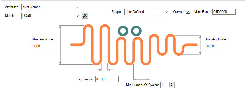
The Serpentine Rules dialog is used to specify the shape, amplitude and other parameters of a Serpentine Routing pattern when defined for a track.
The general rule matching mechanism is described here.
Shortcuts
Menu: Setup
Default Keys: T
Command: Technology
Locating this option
Available from: Setup menu > Technology option > Rules - High Speed - Serpentine page
Using the Serpentine Rules dialog
On selection, the Technology dialog opens, select Serpentine. The existing Serpentine Rules for the Technology being used will be presented.

Navigation
The buttons to the right side of the dialog are used to navigate the grid, the general common buttons are detailed on the Technology Navigation page.
Using the editing pane

The appropriate Serpentine rule is found for each net item by working down the list of rules until the first
match is found. Hence, the order of the rules is important. A match is when the specified Attribute Name
and Match Value match attributes of a net item. So the Serpentine rule must have the given attribute,
and it’s value must wildcard match the value. By adding an
attribute to a net item, you can cause it to receive a different shaped Serpentine shape or parameters.
The Wildcard Wizard is enabled using the small icon next
to the Match Value entry: ![]()
Shape
There are four basic shapes for the serpentine plus a user-defined shape which can be formed by customising one of the other four shapes. The four shapes available are - 180 Degree Curved, Orthogonal, Sawtooth and Trombone.
-
180 Degree Curved - ‘curved’ corners

-
Orthogonal - same as 180 degree curved but with Mitre corners

-
Sawtooth - made up from 45 degree edges

-
Trombone - this shape style extends the extra tracking length from one side of the selected track. Two styles are available for Trombone - Octagonal and Curved. These are selected using the Curved check box.

For each shape, you can specify whether the corners are Curved or not by selecting the check box.
For each shape, you can also specify the Mitre Ratio, see below
Mitre Ratio and Amplitude
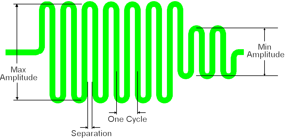
To fully define a Serpentine Route you need the amplitude and the separation.
The amplitude is the distance from the top to the bottom of the perpendicular segments, this includes the semi-circular sections, but does not include the width of the track.
The separation is the distance between successive perpendicular segments, excluding the track width.
You can define two amplitudes, a maximum Max Amplitude which is the default, and a minimum Min Amplitude which is used if the maximum would cause a spacing rule error. If the minimum would also cause an error, then no serpentine routing is added in that section.
You can also specify the minimum number of cycles, a cycle being a full up and down ‘loop’. This minimum number of cycles defines the minimum size of a serpentine section and is also used as the minimum length of a straight section caused by an obstacle.
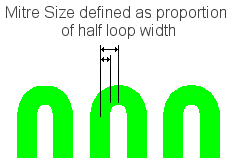
You can control the shape of the top of each loop. The mitre around each turn can be curved or straight, and the size of the mitre is defined by the Mitre Ratio, which is the proportion of the 90 degree corner taken up by the mitre. A value of 1.0 gives a complete 180 degree curve (or sawtooth if straight) around the top of the loop; a value of 0.0 gives a squared off top to the loop; values in between give a loop of two curves or 45 degree angled lines with a flat top between. The default is Curved with a Mitre Ratio of 1.0, which results in 180 degree curve around the loop. A Mitre Ratio of 0.585786 and straight mitre gives an octagonal shape around the loop (angled mitres and flat top with the same length). The drop down list, above the Curved and Mitre Ratio controls, allows you to set the parameters for the most common shapes.
The Mitre Ratio is not relevant if the amplitude is less than half the cycle length, because the size of the mitre is determined by the amplitude alone.


There is a Design Rule Check to ensure that each Serpentine is using the current parameters. Note that if you change the parameters on an individual Serpentine, then you have overridden the rules it is no longer linked to the technology rules.
Export and Import CSV
Use the Export CSV button to export the data in your PCB design into a CSV format file. Using the Export CSV option will provide you with a formatted template ready for you to edit in your own data.
Use the Import CSV button to import data back into the PCB design using a CSV format file.
The data in the file represents a spreadsheet of dialog contents with the data headings along the top row.
Related Topics
Technology Overview | Using Dialog Grids | Serpentine Routing | Design Rule Check | Export CSV | Import CSV