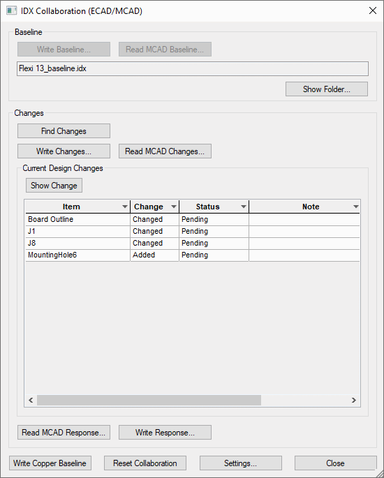
This page describes the workflow that would be used for the IDX Collaboration option. The workflow depends on how you start the process, whether you use Pulsonix PCB to MCAD or MCAD to PCB. Both process are described below. There are variations so the basic process is described.
Locating this option
Available from: 3D Design menu > IDX Collaboration option
Pulsonix PCB to MCAD
Workflow Overview
You have created your PCB using a board outline, critical component placement and mounting holes etc. in Pulsonix PCB. You now wish to ‘push’ the design into your MCAD system for viewing or checking.

Writing an IDX baseline will happen once at the very start of the collaboration so that both ECAD and MCAD are synchronised. Afterwards, both the workflows described above (ECAD to MCAD, and MCAD to ECAD, minus the writing/reading of a baseline) are expected to happen numerous times in the design process, sending change files and response files to each other until the design in finalised.
-
Write Baseline Provides a starting point and is the first file written. This could be considered the master file from which all other changes are based.
-
Run Find Changes to inform you of changes made to the design. At this point you can move on to Write Changes, or:
-
You may decide to make further PCB changes to your PCB design.
Back in the IDX Collaboration dialog, you will run Find Changes again to read latest changes.
This can be an iterative process.
At some point, you may decide to commit the changes and will Write Changes to a changes file.
-
In the MCAD system, Accept Changes and write a response.
-
Back in PCB - Read MCAD Response. At this point a Clearance file is automatically generated. It acts as a ‘receipt’ that both designs have processed the change.
Note: This is not necessarily present in all implementations of IDX.
-
If MCAD has made changes you do read them in using Read MCAD Changes, and this will automatically populate the grid with these changes (the Find Changes button will not be used, as this finds the changes between your current PCB design and the current IDX Baseline file).
MCAD to Pulsonix PCB
Workflow Overview
You have want to start by creating your board outline in the MCAD system. Your board must fit the enclosure size for example. You may also need to create mounting holes to fit and place critical components etc. You will now write an IDX file that can be pulled into your PCB to start the design or add information to an existing design.
- You have want to start by creating your board outline and other critical items required in your MCAD system. Your board must fit the enclosure size for example. You may also need to create mounting holes to fit and place critical components etc.
- You will now write an IDX baseline file that can be ‘pulled’ into your PCB to start the design or add information to an existing design.
- In Pulsonix, in the IDX Collaboration dialog you will select Read MCAD Baseline
- Once a change file has been read in, the grid is populated with all the changes present in the file.
- You can use the Show Change button on a selected item to highlight the item in the design.
- The ‘Response’ column is now visible in the grid, and allows toggling between accepting and rejecting each change. (Note: You can use the ‘Show Change’ button, or double click on a grid row to show the selected change in your design).
- Once you are happy with the accept/reject state of the changes, use the Write Response option to generate an IDX response file for the changes. This should be read in by MCAD, which will accept/reject the changes in their design, so that both designs are synchronised.