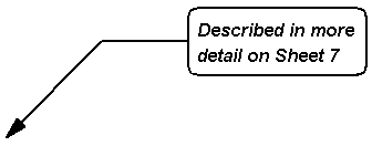
In a Schematic design, PCB design or in a Symbol, it is possible to interactively create a text callout, like the one shown below, that labels a point of interest with a text item. These give you a method of documenting a specific point in the design with detailed information.
You can also attach callouts to design items, such as components or to a Symbol Pin, to document information about the item. Once attached, you can substitute any of the item’s attribute values into the callout text. When the item is moved, the attached end of the callout is also moved to keep it with the item of interest.
One use for this is to display the net name on a schematic pin, surrounded by a box.

Shortcuts
Default Keys: None
Default Menu: Insert
Command: Insert Text Callout
Locating this option
Available from: Insert menu > Text Callout > option
Callout Appearance
A callout is automatically constructed with shapes and a multi-line text item using styles defined in the Text Callout Defaults dialog. This dialog defines the Layer, Line Style, Text Style for the callout, along with some parameters that describe the callout appearance. For example, you can change the shape of the box surrounding the text, change the type of pointer symbol at end of the callout line and its position on the callout box.
As these values do not vary much, they can be set up in your Technology File and Text Callout Defaults ready for use on new designs.
Once a callout has been added to the design, if you have changed its style and appearance from the default settings, you can copy these properties for your next callout by selecting the existing callout prior to using the Insert Text Callout option again. The new callout will inherit the properties of the selected one.
Once used in the design, you can also use Text Callout Properties to alter the Text Callout appearance.
How To Insert A Callout
Follow this procedure to add a text callout to a design:
-
Select Text Callout from the Insert menu in a design, or from the Toolbar. A callout cursor will be displayed whilst adding the callout.
-
Pick the starting point of the callout, the point that the callout will refer to. If you want to attach the callout to an item, like a component for example, make sure the Attach Callouts option is checked by right clicking and using the context menu. Select the item you want to attach the callout to. Using Shift+Select on a shape will attach the callout to the nearest point on a shape.
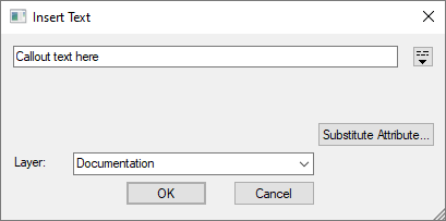
The Insert Text dialog will be displayed (if adding a Callout in a PCB design):

-
Type in the text you want displayed in the callout. If you want multi-line text click on the multi-line icon to the right of the text box to allow entry of multiple lines.
-
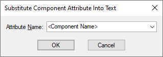
Use the Substitute Attribute button to paste an attribute name into the callout text in such a way that it will be substituted with the attribute value when the callout is added to the design.
Choose the attribute you want substituted from the drop down list presented. The list is in context to the item selected:

Press OK to paste its name into the callout text, encapsulated with the correct substitution character.
-
If editing a Schematic design you can choose to put the text callout only on the current page (the default) or All Pages At This Level.
If editing a PCB design, use the Layer drop down list to select the layer that you want the callout to appear on.
-
Press OK to accept the callout text.
-
The dialog is removed and a callout is displayed with the text portion of the callout placed on your cursor for you to position in the design.
-
Move the mouse to position the text item. The pointer line will be automatically updated to fit with the position of the text.
-
Right click and use Change Layer from the context menu if you wish to change the layer the callout is on.
-
Click the mouse button again to finish the callout at the required position. Another callout will be automatically be started.
-
When you have added as many callouts as you require, use the Esc key or Cancel from the context menu to abort the next callout being added and exit the option.
How To Change A Text Callout
Once completed, a text callout can be moved, rotated and flipped like any other item.
You can also stretch the callout by dragging either the text item, or the pointer at the other end of the callout line. This allows you to either reposition the point of interest, or simply move the text item to a more readable position. If the callout is attached to an item, then moving the item will dynamically move the pointer end of the callout to keep it on the item.
Callout Properties
If you wish to change a callout Layer, Styles, appearance and text contents, double-click on the callout or select it and right click to use Properties.
Unattaching Callout
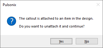
The callout will be ‘attached’. To unattach it from an item, when you drag the attached end near the arrow or pointer, you will get the following message.

Press Yes to unattach the callout and allow the pointer end to be moved and attached to another item. Press No to cancel this action.
Hyperlinks
You can use Execute Hyperlink on a callout from the
context menu if the callout text is suitable, or if the callout is attached to an item that has the
If you select the callout text, Execute Hyperlink will use the text as the link to follow. If you
select the complete callout or and any callout lines, Execute Hyperlink will first try to use the
Text Callouts in Variants
When using Design Variants, a text callout can be set to only appear in the required variants.
Alternatively, the attribute substitution facility described above makes it possible for a text callout to derive its variant behaviour from a referenced design level attribute.
If the design level attribute is defined to be variant specific, then a text callout that uses it as a substituted attribute will only appear in the same variants.
Related Topics
Move | Stretching A Callout | Technology - Layers | Technology - Text Styles | Text Callout Defaults | Text Callout Properties | Design Variants | Design variant Properties | Execute Hyperlink | Attribute Substitution